Example for Configuring Basic VPWS QoS Functions
After you configure basic VPWS QoS functions, you can check the bandwidth specified for each VPWS PW.
Networking Requirements
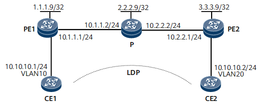
On the network shown in Figure 1, CE1 and CE2 connect to PE1 and PE2 through VLANs, respectively.
An LDP VPWS PW needs to be established between PE1 and PE2. PE2 needs to restrict the bandwidth of inbound traffic from its user side to ensure that the traffic from CE2 to CE1 enjoys a CIR of 2000 kbit/s and a PIR of 3000 kbit/s.
Device Name |
Interface |
IP Address and Mask |
|---|---|---|
CE1 |
GE0/1/0.1 |
10.10.10.1/24 |
PE1 |
Loopback1 |
1.1.1.9/32 |
GE0/1/8 |
10.1.1.1/24 |
|
P |
Loopback1 |
2.2.2.9/32 |
GE0/1/0 |
10.2.2.2/24 |
|
GE0/1/8 |
10.1.1.2/24 |
|
PE2 |
Loopback1 |
3.3.3.9/32 |
GE0/1/0 |
10.2.2.1/24 |
|
CE2 |
GE0/1/0.1 |
10.10.10.2/24 |
Configuration Roadmap
The configuration roadmap is as follows:
Configure a routing protocol on PEs and the P on the backbone network to achieve connectivity between these devices and enable MPLS on them.
Establish a TE tunnel between PEs to transmit user data, and configure a tunnel policy in which the TE tunnel is preferentially selected.
Enable MPLS L2VPN on PEs and create VCs.
Configure VLAN sub-interfaces so that CEs can access PEs through VLANs.
Configure QoS parameters on GE 0/1/0.1 of PE2.
Data Preparation
To complete the configuration, you need the following data:
VLAN sub-interface numbers
Name of the remote peer of each PE
VC ID
CIR
PIR
Procedure
- Configure basic functions on CEs.
# Configure CE1.
<HUAWEI> system-view
[~HUAWEI] sysname CE1
[*HUAWEI] commit
[~CE1] interface gigabitethernet 0/1/0
[~CE1-GigabitEthernet0/1/0] undo shutdown
[*CE1-GigabitEthernet0/1/0] quit
[*CE1] interface gigabitethernet 0/1/0.1
[*CE1-GigabitEthernet0/1/0.1] vlan-type dot1q 10
[*CE1-GigabitEthernet0/1/0.1] ip address 10.10.10.1 24
[*CE1-GigabitEthernet0/1/0.1] quit
[*CE1] commit
# Configure CE2.
<HUAWEI> system-view
[~HUAWEI] sysname CE2
[*HUAWEI] commit
[~CE2] interface gigabitethernet 0/1/0
[~CE2-GigabitEthernet0/1/0] undo shutdown
[*CE2-GigabitEthernet0/1/0] quit
[*CE2] interface gigabitethernet 0/1/0.1
[*CE2-GigabitEthernet0/1/0.1] vlan-type dot1q 20
[*CE2-GigabitEthernet0/1/0.1] ip address 10.10.10.2 24
[*CE2-GigabitEthernet0/1/0.1] quit
[*CE2] commit
- Configure an IGP on the MPLS backbone network. OSPF is used in this example.
Assign an IP address to each interface on PEs and the P based on Figure 1. When configuring OSPF, advertise the 32-bit IP addresses of loopback interfaces, which are used as LSR IDs, on the PEs and P.
- Configure an MPLS TE tunnel.
- Establish a remote LDP session between PEs.
# Configure PE1.
[~PE1] mpls ldp
[*PE1] mpls ldp remote-peer 3.3.3.9
[*PE1-mpls-ldp-remote-3.3.3.9] remote-ip 3.3.3.9
[*PE1-mpls-ldp-remote-3.3.3.9] quit
[*PE1] commit
# Configure PE2.
[~PE2] mpls ldp
[~PE2] mpls ldp remote-peer 1.1.1.9
[*PE2-mpls-ldp-remote-1.1.1.9] remote-ip 1.1.1.9
[*PE2-mpls-ldp-remote-1.1.1.9] quit
[*PE2] commit
After the configuration is complete, run the display mpls ldp session command on PE1 to check LDP session information. The command output shows that PE1 has established an LDP session with PE2.
The following example uses the command output on PE1.
[~PE1] display mpls ldp session
LDP Session(s) in Public Network
 LAM : Label Advertisement Mode      SsnAge Unit : DDDD:HH:MM
 An asterisk (*) before a session means the session is being deleted.
 ------------------------------------------------------------------------------
 Peer-ID            Status      LAM  SsnRole  SsnAge      KA-Sent/Rcv
 ------------------------------------------------------------------------------
 3.3.3.9:0          Operational DU   Passive  0000:00:09   37/37
 ------------------------------------------------------------------------------
TOTAL: 1 session(s) Found.
- Configure a tunnel policy in which the TE tunnel is preferentially selected and establish a VPWS connection.
# Configure PE1.
[~PE1] tunnel-policy policy1
[*PE1-tunnel-policy-policy1] tunnel select-seq te load-balance-number 1
[*PE1-tunnel-policy-policy1] quit
[*PE1] mpls l2vpn
[*PE1-l2vpn] quit
[*PE1] interface gigabitethernet 0/1/0
[*PE1-GigabitEthernet0/1/0] undo shutdown
[*PE1-GigabitEthernet0/1/0] quit
[*PE1] interface gigabitethernet 0/1/0.1
[*PE1-GigabitEthernet0/1/0.1] vlan-type dot1q 10
[*PE1-GigabitEthernet0/1/0.1] mpls l2vc 3.3.3.9 101 tunnel-policy policy1
[*PE1-GigabitEthernet0/1/0.1] quit
[*PE1] commit
# Configure PE2.
[~PE2] tunnel-policy policy1
[*PE2-tunnel-policy-policy1] tunnel select-seq te load-balance-number 1
[*PE2-tunnel-policy-policy1] quit
[*PE2] mpls l2vpn
[*PE2-l2vpn] quit
[*PE2] interface gigabitethernet 0/1/8
[*PE2-GigabitEthernet0/1/8] undo shutdown
[*PE2-GigabitEthernet0/1/8] quit
[*PE2] interface gigabitethernet 0/1/8.1
[*PE2-GigabitEthernet0/1/8.1] vlan-type dot1q 20
[*PE2-GigabitEthernet0/1/8.1] mpls l2vc 1.1.1.9 101 tunnel-policy policy1
[*PE2-GigabitEthernet0/1/8.1] quit
[*PE2] commit
- Configure QoS parameters on GE0/1/8.1 of PE2 to ensure VPWS bandwidth.
# Configure QoS parameters.
[~PE2] interface gigabitethernet 0/1/8.1
[~PE2-GigabitEthernet0/1/8.1] mpls l2vpn qos cir 2000 pir 3000
[*PE2-GigabitEthernet0/1/8.1] quit
[*PE2] commit
- Verify the configuration.
Check L2VPN connection information on PEs. You can find that an L2VC has been established and is up.
The following example uses the command output on PE2.
[~PE2] display mpls l2vc interface gigabitethernet 0/1/8.1
 *client interface          : GigabitEthernet0/1/8.1 is up
  session state             : up
  AC status                 : up
  VC state                  : up
  VC ID                     : 101
  VC type                   : VLAN
  destination               : 1.1.1.9
  local group ID            : 0            remote group ID      : 0
  local VC label            : 21504        remote VC label      : 21504
  local AC OAM State        : up
  local PSN State           : up
  local forwarding state    : forwarding
  remote AC OAM state       : up
  remote PSN state          : up
  remote forwarding state   : forwarding
  BFD for PW                : disable
  manual fault              : not set
  active state              : active
  forwarding entry          : exist
  link state                : up
  local VC MTU              : 1500         remote VC MTU        : 1500
  local VCCV                : Disable
  remote VCCV               : Disable
  local control word        : disable      remote control word  : disable
  tunnel policy name        : --
  traffic behavior name     : --
  PW template name          : --
  primary  or secondary     : primary
  VC tunnel/token info      : 1 tunnels/tokens
    NO.0  TNL type : lsp   , TNL ID : 0x2002003
  create time               : 0 days, 0 hours, 4 minutes, 19 seconds
  up time                   : 0 days, 0 hours, 2 minutes, 40 seconds
  last change time          : 0 days, 0 hours, 2 minutes, 40 seconds
  VC last up time           : 2014/08/22 12:31:31
  VC total up time          : 0 days, 2 hours, 12 minutes, 51 seconds
  CKey                      : 2
  NKey                      : 1
  L2VPN QoS CIR value       : 2000
  L2VPN QoS PIR value       : 3000
  L2VPN QoS qos-profile name: --
  PW redundancy mode        : frr
  AdminPw interface         : --
  AdminPw link state        : --
  Forward state             : send inactive, receive inactive
  Diffserv Mode             : uniform
  Service Class             : --
  Color                     : --
  DomainId                  : --
  Domain Name               : --
CE1 and CE2 can ping each other.
The following example uses the command output on CE1.
[~CE1] ping 10.10.10.2
  PING 10.10.10.2: 56  data bytes, press CTRL_C to break
    Reply from 10.10.10.2: bytes=56 Sequence=1 ttl=255 time=31 ms
    Reply from 10.10.10.2: bytes=56 Sequence=2 ttl=255 time=10 ms
    Reply from 10.10.10.2: bytes=56 Sequence=3 ttl=255 time=5 ms
    Reply from 10.10.10.2: bytes=56 Sequence=4 ttl=255 time=2 ms
    Reply from 10.10.10.2: bytes=56 Sequence=5 ttl=255 time=28 ms
  --- 10.10.10.2 ping statistics ---
    5 packet(s) transmitted
    5 packet(s) received
    0.00% packet loss
    round-trip min/avg/max = 2/15/31 ms
Configuration Files
CE1 configuration file
#
sysname CE1
#
interface GigabitEthernet0/1/0
 undo shutdown
#
interface GigabitEthernet0/1/0.1
 vlan-type dot1q 10
 ip address 10.10.10.1 255.255.255.0
#
return
PE1 configuration file
#
sysname PE1
#
mpls lsr-id 1.1.1.9
#
mpls
 mpls te
 mpls rsvp-te
 mpls te cspf
#
mpls l2vpn
#
mpls ldp
#
mpls ldp remote-peer 3.3.3.9
 remote-ip 3.3.3.9
#
interface GigabitEthernet0/1/0
 undo shutdown
#
interface GigabitEthernet0/1/0.1
 vlan-type dot1q 10
 mpls l2vc 3.3.3.9 101 tunnel-policy policy1
 mpls l2vpn qos cir 2000 pir 3000
#
interface GigabitEthernet0/1/8
 undo shutdown
 ip address 10.1.1.1 255.255.255.0
 mpls
 mpls te
 mpls te bandwidth max-reservable-bandwidth 5000
 mpls te bandwidth bc0 4000
 mpls rsvp-te
#
interface LoopBack1
 ip address 1.1.1.9 255.255.255.255
#
interface Tunnel10
 ip address unnumbered interface LoopBack1
 tunnel-protocol mpls te
 mpls te signal-protocol rsvp-te
 destination 3.3.3.9
 mpls te bandwidth ct0 2000
 mpls te tunnel-id 101
#
ospf 1
 opaque-capability enable
 area 0.0.0.0
  network 1.1.1.9 0.0.0.0
  network 10.1.1.0 0.0.0.255
  mpls-te enable
#
tunnel-policy policy1
 tunnel select-seq te load-balance-number 1
#
return
P configuration file
#
sysname P
#
mpls lsr-id 2.2.2.9
#
mpls
 mpls te
 mpls rsvp-te
 mpls te cspf
#
interface GigabitEthernet0/1/0
 undo shutdown
 ip address 10.2.2.2 255.255.255.0
 mpls
 mpls te
 mpls te bandwidth max-reservable-bandwidth 5000
 mpls te bandwidth bc0 4000
 mpls rsvp-te
#
interface GigabitEthernet0/1/8
 undo shutdown
 ip address 10.1.1.2 255.255.255.0
 mpls
 mpls te
 mpls te bandwidth max-reservable-bandwidth 5000
 mpls te bandwidth bc0 4000
 mpls rsvp-te
#
interface LoopBack1
 ip address 2.2.2.9 255.255.255.255
#
ospf 1
#
 opaque-capability enable
 area 0.0.0.0
  network 2.2.2.9 0.0.0.0
  network 10.1.1.0 0.0.0.255
  network 10.2.2.0 0.0.0.255
  mpls-te enable
#
return
PE2 configuration file
#
sysname PE2
#
mpls lsr-id 3.3.3.9
#
mpls
 mpls te
 mpls rsvp-te
 mpls te cspf
#
mpls l2vpn
#
mpls ldp
#
mpls ldp remote-peer 1.1.1.9
 remote-ip 1.1.1.9
#
interface GigabitEthernet0/1/0
 undo shutdown
 ip address 10.2.2.1 255.255.255.0
 mpls
 mpls te
 mpls te bandwidth max-reservable-bandwidth 5000
 mpls te bandwidth bc0 4000
 mpls rsvp-te
#
interface GigabitEthernet0/1/8
 undo shutdown
#
interface GigabitEthernet0/1/8.1
 vlan-type dot1q 20
 mpls l2vc 1.1.1.9 101 tunnel-policy policy1
 mpls l2vpn qos cir 2000 pir 3000
#
interface LoopBack1
 ip address 3.3.3.9 255.255.255.255
#
interface Tunnel10
 ip address unnumbered interface LoopBack1
 tunnel-protocol mpls te
 mpls te signal-protocol rsvp-te
 destination 1.1.1.9
 mpls te bandwidth ct0 2000
 mpls te tunnel-id 101
#
ospf 1
 opaque-capability enable
 area 0.0.0.0
  network 3.3.3.9 0.0.0.0
  network 10.2.2.0 0.0.0.255
  mpls-te enable
#
tunnel-policy policy1
 tunnel select-seq te load-balance-number 1
#
return
CE2 configuration file
#
sysname CE2
#
interface GigabitEthernet0/1/0
 undo shutdown
#
interface GigabitEthernet0/1/0.1
 vlan-type dot1q 20
 ip address 10.10.10.2 255.255.255.0
#
return