Configuring PW Redundancy
To build a virtual leased line from a BTS to a BSC, you can configure single-segments PWs or multi-segment PWs between CSGs and RSGs.
Usage Scenario
Network deployment imposes high requirements for VPN services. There are many fast fault detection and protection switching mechanisms such as bidirectional forwarding detection (BFD), operation, administration and maintenance (OAM), and fast reroute (FRR). These mechanisms, however, address only link or node failures within a packet switched network (PSN), but not PE failures or attachment circuit (AC) failures between PEs and CEs.
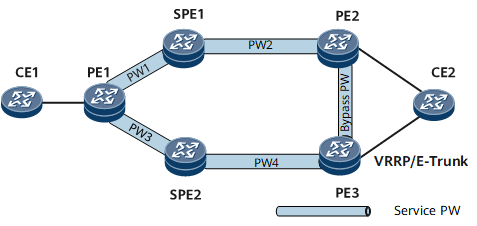
On the network shown in Figure 1 multi-segment PW services have been deployed between PE1 and PE2. To improve network reliability, configure PW redundancy on the SPE or PE1.

- Only PWE3 VPWS supports PW redundancy. After the mpls l2vpn default martini command is run, VPWS does not support PW redundancy any longer.
- When configuring PW redundancy, be sure to configure the primary, secondary, and bypass PW parameters consistently. Otherwise, the secondary or bypass PW may fail to take over services when the primary PW fails.
After configuring the primary and secondary PWs on a PE, you can specify the PW redundancy mode. The following PW redundancy modes are supported:
FRR mode: The FRR mode is the default PW redundancy mode and does not need to be configured.
Negotiation: is configured by using the mpls l2vpn redundancy command.
Master/slave mode: The primary and secondary PWs are manually specified on the master device, and then the local device notifies the remote device of information about the primary and secondary PWs. PW redundancy in master/slave mode works with the bypass PW to prevent links on the network side and links on the AC side from sensing faults in each other. That is, the fault on the AC side will trigger only an AC switchover and the fault on the public network will trigger only a PW switchover.
Independent mode: The primary and secondary PWs are determined by means of negotiation. Two PWs are configured on one PE to connect to two peer PEs, with both PWs being in the primary state on the local device. The peer PEs determine the primary and secondary PWs by means of E-Trunk or mVRRP, with one PW in the primary state and the other in the secondary state. The PEs on both ends negotiate and finally determine the primary PW. The independent mode applies to scenarios where PW redundancy is associated with E-Trunk. PW redundancy in independent mode, together with the bypass PW, can prevent links on the AC side from sensing faults on the network side but cannot prevent links on the network side from sensing faults on the AC side. That is, the fault on the public network will trigger only a PW switchover but not an AC link switchover whereas the fault on the AC side will trigger both an AC switchover and a PW switchover.
Pre-configuration Tasks
Before configuring PW redundancy, complete the following tasks:
Configuring IP addresses and an IGP on PEs
Configuring basic MPLS functions on the PEs
Establish a public network tunnel between PE1 and SPE and between the PE2 and the PE3. The public network tunnel can be LDP or TE.
- Configuring the Master/Slave Mode of PW Redundancy
- PW redundancy in master/slave mode implements fault isolation for public and AC links.
- Configuring the Independent PW Redundancy Mode
- The independent PW redundancy mode allows a public network fault to trigger only the public network link switchover.
- Configuring PW Status Negotiation
- In PW redundancy in Independent mode, the master/backup status of the local PE is determined by the status of signaling sent from the remote PE.
- Binding Service PWs to an mPW
- After service PWs are bound to an mPW, the service PW status is determined by the mPW status.
- Configuring BFD for VPWS PW
- Configuring BFD for VPWS PW accelerates PW fault detection, resulting in fast switching of upper-layer applications.
- (Optional) Configuring a switching delay for the PW switching
- When a switching delay is configured for a PW, the master PW fails, the traffic switches to the slave PW after the delay period expires.