Example for Configuring PW APS for Dynamic MS-PWs
In PW APS scenarios, MPLS OAM is used to detect the status of dynamic MS-PWs.
Networking Requirements

This chapter applies only to the NetEngine 8000 F1A.
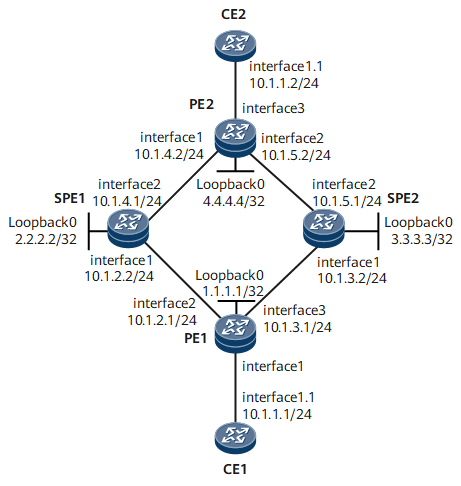
On the public network shown in Figure 1, dynamic associated bidirectional LSPs need to be established between the four PEs. In addition, CE1 and CE2 need to reliably communicate through the four PEs on the public network.
PW redundancy needs to be deployed on PE1 and PE2. For primary and secondary PWs that share the same source and same destination and dynamic associated bidirectional LSPs, consider deploying PW APS for dynamic PWs. As the four PEs belong to different IGP domains, the PWs must be MS-PWs.
Configuration Roadmap
The configuration roadmap is as follows:
Configure interface IP addresses and a routing protocol.
Configure MPLS and public network tunnels.
In this example, dynamic associated bidirectional LSPs are used between PEs and SPEs. The specific configurations include:
Configure basic MPLS functions and enable MPLS TE, RSVP-TE, and CSPF.
Configure OSPF TE.
Configure dynamic associated bidirectional LSPs.
Configure a PW protection group (dynamic MS-PWs are used in this example), which includes:
Configure a PW protection group on PE1 and PE2.
Configure a dynamic switched PW on SPE1 and SPE2.
Configure PW APS, which includes:
Configure a PW APS instance on PE1 and PE2.
Bind the PW protection group to the PW APS instance.
Configure MPLS OAM to detect PW status.
Configure CEs to access the L2VPN through VLANs on the AC side.
Data Preparation
To complete the configuration, you need the following data:
PEs' interface numbers, IP addresses and OSPF process IDs
Each PE's LSR ID, tunnel interface numbers and IP addresses, and tunnel IDs and ingress LSR IDs of reverse RSVP LSPs
Local and remote IP addresses, VC IDs, and VC types of L2VCs
APS instance numbers on PE1 and PE2
Procedure
- Configure interface IP addresses and a routing protocol.
Assign an IP address and mask to each interface according to Figure 1. The configuration details are not provided.
In this example, OSPF is used as the IGP for PE1, PE2, SPE1, and SPE2 to communicate at the network layer. The configuration details are not provided here.
- Configure MPLS and public network tunnels.
In this example, dynamic associated bidirectional LSPs are used between PEs (PE1 and PE2) and SPEs (SPE1 and SPE2).
- Configure a PW protection group.
Dynamic MS-PWs are used in this example.
- Configure PW APS.
- Configure MPLS OAM to detect PW status.
# Configure PE1.
[~PE1] mpls
[*PE1-mpls] mpls oam
[*PE1-mpls] quit
[*PE1] mpls-oam
[*PE1-mpls-oam] mpls oam l2vc peer-ip 2.2.2.2 vc-id 1 vc-type vlan remote-peer-ip 4.4.4.4 remote-vc-id 3 remote-vc-type vlan type cv auto-protocol
[*PE1-mpls-oam] mpls oam l2vc peer-ip 3.3.3.3 vc-id 2 vc-type vlan remote-peer-ip 4.4.4.4 remote-vc-id 4 remote-vc-type vlan type cv auto-protocol
[*PE1-mpls-oam] mpls oam l2vc enable receive peer-ip 2.2.2.2 vc-id 1 vc-type vlan
[*PE1-mpls-oam] mpls oam l2vc enable send peer-ip 2.2.2.2 vc-id 1 vc-type vlan
[*PE1-mpls-oam] mpls oam l2vc enable receive peer-ip 3.3.3.3 vc-id 2 vc-type vlan
[*PE1-mpls-oam] mpls oam l2vc enable send peer-ip 3.3.3.3 vc-id 2 vc-type vlan
[*PE1-mpls-oam] quit
[*PE1] commit
# Configure PE2.
[~PE2] mpls
[*PE2-mpls] mpls oam
[*PE2-mpls] quit
[*PE2] mpls-oam
[*PE2-mpls-oam] mpls oam l2vc peer-ip 2.2.2.2 vc-id 3 vc-type vlan remote-peer-ip 1.1.1.1 remote-vc-id 1 remote-vc-type vlan type cv auto-protocol
[*PE2-mpls-oam] mpls oam l2vc peer-ip 3.3.3.3 vc-id 4 vc-type vlan remote-peer-ip 1.1.1.1 remote-vc-id 2 remote-vc-type vlan type cv auto-protocol
[*PE2-mpls-oam] mpls oam l2vc enable receive peer-ip 2.2.2.2 vc-id 3 vc-type vlan
[*PE2-mpls-oam] mpls oam l2vc enable send peer-ip 2.2.2.2 vc-id 3 vc-type vlan
[*PE2-mpls-oam] mpls oam l2vc enable receive peer-ip 3.3.3.3 vc-id 4 vc-type vlan
[*PE2-mpls-oam] mpls oam l2vc enable send peer-ip 3.3.3.3 vc-id 4 vc-type vlan
[*PE2-mpls-oam] quit
[*PE2] commit
Check MPLS OAM information on PE1.
[~PE1] display mpls oam l2vc all -------------------------------------------------------------------------------- Total Oam Num: 2 Total Start Oam Num: 2 Total Defect Oam Num: 0 -------------------------------------------------------------------------------- No. Peer IP VC Type VC ID Status -------------------------------------------------------------------------------- 1 2.2.2.2 vlan 3 Start/Non-defect 2 3.3.3.3 vlan 4 Start/Non-defect - Verify the configuration.
# Ping a GE sub-interface of CE2 from CE1.
[~CE1] ping 10.1.1.2
PING 10.1.1.2: 56  data bytes, press CTRL_C to break
    Reply from 10.1.1.2: bytes=56 Sequence=1 ttl=255 time=40 ms
    Reply from 10.1.1.2: bytes=56 Sequence=2 ttl=255 time=30 ms
    Reply from 10.1.1.2: bytes=56 Sequence=3 ttl=255 time=40 ms
    Reply from 10.1.1.2: bytes=56 Sequence=4 ttl=255 time=1 ms
    Reply from 10.1.1.2: bytes=56 Sequence=5 ttl=255 time=1 ms

  --- 10.1.1.2 ping statistics ---
    5 packet(s) transmitted
    5 packet(s) received
    0.00% packet loss
    round-trip min/avg/max = 1/22/40 ms
Configuration Files
CE1 configuration file
#
sysname CE1
#
interface GigabitEthernet0/1/0
 undo shutdown
#
interface GigabitEthernet0/1/0.1
 vlan-type dot1q 10
 ip address 10.1.1.1 255.255.255.0
#
return
PE1 configuration file
#
sysname PE1
#
vlan batch 10
#
mpls lsr-id 1.1.1.1
mpls
 mpls te
 label advertise non-null
 mpls rsvp-te
 mpls oam
 mpls te cspf
#
mpls l2vpn
#
pw-aps 1
#
explicit-path 1to2
 next hop 10.1.2.2
 next hop 2.2.2.2
#
explicit-path 1to3
 next hop 10.1.3.2
 next hop 3.3.3.3
#
mpls ldp
#
mpls ldp remote-peer 2.2.2.2
 remote-ip 2.2.2.2
#
mpls ldp remote-peer 3.3.3.3
 remote-ip 3.3.3.3
#
interface Vlanif10
#
interface GigabitEthernet0/1/0
 undo shutdown
#
interface GigabitEthernet0/1/0.1
 vlan-type dot1q 10
 mpls l2vc 2.2.2.2 1 tunnel-policy policy1 control-word
 mpls l2vc 3.3.3.3 2 tunnel-policy policy1 control-word secondary
 mpls l2vpn pw-aps 1 admin
#
interface GigabitEthernet0/1/1
 undo shutdown
 ip address 10.1.2.1 255.255.255.0
 mpls
 mpls te
 mpls rsvp-te
#
interface GigabitEthernet0/1/2
 undo shutdown
 ip address 10.1.3.1 255.255.255.0
 mpls
 mpls te
 mpls rsvp-te
#
interface LoopBack0
 ip address 1.1.1.1 255.255.255.255
#
interface Tunnel10
 ip address unnumbered interface LoopBack0
 tunnel-protocol mpls te
 destination 2.2.2.2
 mpls te tunnel-id 100
 mpls te reverse-lsp protocol rsvp-te ingress-lsr-id 2.2.2.2 tunnel-id 100
 mpls te path explicit-path 1to2
 mpls te reserved-for-binding
#
interface Tunnel11
 ip address unnumbered interface LoopBack0
 tunnel-protocol mpls te
 destination 3.3.3.3
 mpls te tunnel-id 200
 mpls te reverse-lsp protocol rsvp-te ingress-lsr-id 3.3.3.3 tunnel-id 200
 mpls te path explicit-path 1to3
 mpls te reserved-for-binding
#
ospf 1
 opaque-capability enable
 area 0.0.0.0
  network 10.1.2.0 0.0.0.255
  network 1.1.1.1 0.0.0.0
  network 10.1.3.0 0.0.0.255
  mpls-te enable
#
tunnel-policy policy1
 tunnel binding destination 2.2.2.2 te Tunnel10
 tunnel binding destination 3.3.3.3 te Tunnel11
#
mpls-oam
 mpls oam l2vc peer-ip 2.2.2.2 vc-id 1 vc-type vlan remote-peer-ip 4.4.4.4 remote-vc-id 3 remote-vc-type vlan type cv auto-protocol
 mpls oam l2vc peer-ip 3.3.3.3 vc-id 2 vc-type vlan remote-peer-ip 4.4.4.4 remote-vc-id 4 remote-vc-type vlan type cv auto-protocol
 mpls oam l2vc enable receive peer-ip 2.2.2.2 vc-id 1 vc-type vlan
 mpls oam l2vc enable send peer-ip 2.2.2.2 vc-id 1 vc-type vlan
 mpls oam l2vc enable receive peer-ip 3.3.3.3 vc-id 2 vc-type vlan
 mpls oam l2vc enable send peer-ip 3.3.3.3 vc-id 2 vc-type vlan
l
#
return
PE2 configuration file
#
sysname PE2
#
mpls lsr-id 4.4.4.4
mpls
 mpls te
 label advertise non-null
 mpls rsvp-te
 mpls oam
 mpls te cspf
#
mpls l2vpn
#
pw-aps 2
#
explicit-path 4to2
 next hop 10.1.4.1
 next hop 2.2.2.2
#
explicit-path 4to3
 next hop 10.1.5.1
 next hop 3.3.3.3
#
mpls ldp
#
mpls ldp remote-peer 2.2.2.2
 remote-ip 2.2.2.2
#
mpls ldp remote-peer 3.3.3.3
 remote-ip 3.3.3.3
#
interface GigabitEthernet0/1/0
 undo shutdown
 ip address 10.1.4.2 255.255.255.0
 mpls
 mpls te
 mpls rsvp-te
 mpls ldp
#
interface GigabitEthernet0/1/1
 undo shutdown
 ip address 10.1.5.2 255.255.255.0
 mpls
 mpls te
 mpls rsvp-te
#
interface GigabitEthernet0/1/2
 undo shutdown
#
interface GigabitEthernet0/1/2.1
 vlan-type dot1q 10
 mpls l2vc 2.2.2.2 3 tunnel-policy policy1 control-word
 mpls l2vc 3.3.3.3 4 tunnel-policy policy1 control-word secondary
 mpls l2vpn pw-aps 2 admin
#
interface LoopBack0
 ip address 4.4.4.4 255.255.255.255
#
interface Tunnel10
 ip address unnumbered interface LoopBack0
 tunnel-protocol mpls te
 destination 3.3.3.3
 mpls te tunnel-id 400
 mpls te reverse-lsp protocol rsvp-te ingress-lsr-id 3.3.3.3 tunnel-id 400
 mpls te path explicit-path 4to3
 mpls te reserved-for-binding
#
interface Tunnel11
 ip address unnumbered interface LoopBack0
 tunnel-protocol mpls te
 destination 2.2.2.2
 mpls te tunnel-id 300
 mpls te reverse-lsp protocol rsvp-te ingress-lsr-id 2.2.2.2 tunnel-id 300
 mpls te path explicit-path 4to2
 mpls te reserved-for-binding
#
ospf 1
 opaque-capability enable
 area 0.0.0.0
  network 10.1.4.0 0.0.0.255
  network 10.1.5.0 0.0.0.255
  network 4.4.4.4 0.0.0.0
  mpls-te enable
#
tunnel-policy policy1
 tunnel binding destination 2.2.2.2 te Tunnel11
 tunnel binding destination 3.3.3.3 te Tunnel10
#
mpls-oam
 mpls oam l2vc peer-ip 2.2.2.2 vc-id 3 vc-type vlan remote-peer-ip 1.1.1.1 remote-vc-id 1 remote-vc-type vlan type cv auto-protocol
 mpls oam l2vc peer-ip 3.3.3.3 vc-id 4 vc-type vlan remote-peer-ip 1.1.1.1 remote-vc-id 2 remote-vc-type vlan type cv auto-protocol
 mpls oam l2vc enable receive peer-ip 2.2.2.2 vc-id 3 vc-type vlan
 mpls oam l2vc enable send peer-ip 2.2.2.2 vc-id 3 vc-type vlan
 mpls oam l2vc enable receive peer-ip 3.3.3.3 vc-id 4 vc-type vlan
 mpls oam l2vc enable send peer-ip 3.3.3.3 vc-id 4 vc-type vlan
#
return
SPE1 configuration file
#
sysname SPE1
#
mpls lsr-id 2.2.2.2
mpls
 mpls te
 label advertise non-null
 mpls rsvp-te
 mpls te cspf
#
mpls l2vpn
#
mpls switch-l2vc 4.4.4.4 3 tunnel-policy policy1 between 1.1.1.1 1 tunnel-policy
 policy1 encapsulation vlan
#
explicit-path 2to1
 next hop 10.1.2.1
 next hop 1.1.1.1
#
explicit-path 2to4
 next hop 10.1.4.2
 next hop 4.4.4.4
#
mpls ldp
#
mpls ldp remote-peer 1.1.1.1
 remote-ip 1.1.1.1
#
mpls ldp remote-peer 4.4.4.4
 remote-ip 4.4.4.4
#
interface GigabitEthernet0/1/0
 undo shutdown
 ip address 10.1.2.2 255.255.255.0
 mpls
 mpls te
 mpls rsvp-te
#
interface GigabitEthernet0/1/1
 undo shutdown
 ip address 10.1.4.1 255.255.255.0
 mpls
 mpls te
 mpls rsvp-te
#
interface LoopBack0
 ip address 2.2.2.2 255.255.255.255
#
interface Tunnel10
 ip address unnumbered interface LoopBack0
 tunnel-protocol mpls te
 destination 1.1.1.1
 mpls te tunnel-id 100
 mpls te reverse-lsp protocol rsvp-te ingress-lsr-id 1.1.1.1 tunnel-id 100
 mpls te path explicit-path 2to1
 mpls te reserved-for-binding
#
interface Tunnel11
 ip address unnumbered interface LoopBack0
 tunnel-protocol mpls te
 destination 4.4.4.4
 mpls te tunnel-id 300
 mpls te reverse-lsp protocol rsvp-te ingress-lsr-id 4.4.4.4 tunnel-id 300
 mpls te path explicit-path 2to4
 mpls te reserved-for-binding
#
ospf 1
 opaque-capability enable
 area 0.0.0.0
  network 2.2.2.2 0.0.0.0
  network 10.1.4.0 0.0.0.255
  network 10.1.2.0 0.0.0.255
  mpls-te enable
#
tunnel-policy policy1
 tunnel binding destination 1.1.1.1 te Tunnel10
 tunnel binding destination 4.4.4.4 te Tunnel11
#
return
SPE2 configuration file
#
sysname SPE2
#
mpls lsr-id 3.3.3.3
mpls
 mpls te
 label advertise non-null
 mpls rsvp-te
 mpls te cspf
#
mpls l2vpn
#
mpls switch-l2vc 4.4.4.4 4 tunnel-policy policy1 between 1.1.1.1 2 tunnel-policy
 policy1 encapsulation vlan control-word-transparent
#
explicit-path 3to1
 next hop 10.1.3.1
 next hop 1.1.1.1
#
explicit-path 3to4
 next hop 10.1.5.2
 next hop 4.4.4.4
#
mpls ldp
#
mpls ldp remote-peer 1.1.1.1
 remote-ip 1.1.1.1
#
mpls ldp remote-peer 4.4.4.4
 remote-ip 4.4.4.4
#
interface GigabitEthernet0/1/0
 undo shutdown
 ip address 10.1.3.2 255.255.255.0
 mpls
 mpls te
 mpls rsvp-te
#
interface GigabitEthernet0/1/1
 undo shutdown
 ip address 10.1.5.1 255.255.255.0
 mpls
 mpls te
 mpls rsvp-te
#
interface LoopBack0
 ip address 3.3.3.3 255.255.255.255
#
interface Tunnel10
 ip address unnumbered interface LoopBack0
 tunnel-protocol mpls te
 destination 4.4.4.4
 mpls te tunnel-id 400
 mpls te reverse-lsp protocol rsvp-te ingress-lsr-id 4.4.4.4 tunnel-id 400
 mpls te path explicit-path 3to4
 mpls te reserved-for-binding
#
interface Tunnel11
 ip address unnumbered interface LoopBack0
 tunnel-protocol mpls te
 destination 1.1.1.1
 mpls te tunnel-id 200
 mpls te reverse-lsp protocol rsvp-te ingress-lsr-id 1.1.1.1 tunnel-id 200
 mpls te path explicit-path 3to1
 mpls te reserved-for-binding
#
ospf 1
 opaque-capability enable
 area 0.0.0.0
  network 3.3.3.3 0.0.0.0
  network 10.1.3.0 0.0.0.255
  network 10.1.4.0 0.0.0.255
  network 10.1.5.0 0.0.0.255
  mpls-te enable
#
tunnel-policy policy1
 tunnel binding destination 1.1.1.1 te Tunnel11
 tunnel binding destination 4.4.4.4 te Tunnel10
#
return
CE2 configuration file
#
sysname CE2
#
interface Vlanif10
 ip address 10.1.1.2 255.255.255.0
#
interface Eth-Trunk10
 portswitch
 port trunk allow-pass vlan 10
 mode lacp-static
#
interface GigabitEthernet0/1/0
 undo shutdown
 eth-trunk 10
#
interface GigabitEthernet0/1/1
 undo shutdown
 eth-trunk 10
#
return