Example for Configuring BGP VPWS FRR - Asymmetric Access of CEs to PEs
If one CE is single-homed to a PE and another CE is dual-homed to two other PEs, you can configure BGP VPWS FRR for the two CEs to communicate.
Networking Requirements
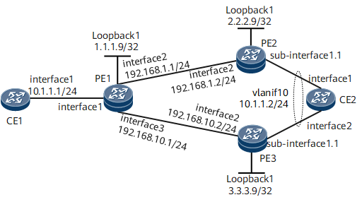
On the network shown in Figure 1, CE1 is single-homed to PE1, and CE2 is dual-homed to PE2 and PE3. A primary BGP VPWS connection needs to be established between PE1 and PE2, and a secondary BGP VPWS connection needs to be established between PE1 and PE3, so that when the primary path CE1 <-> PE1 <-> PE2 <-> CE2 fails, VPWS traffic can be quickly switched to the secondary path CE1 <-> PE1 <-> PE3 <-> CE2.

Configuration Roadmap
The configuration roadmap is as follows:
Configure a routing protocol on the PEs of the backbone network to ensure IP connectivity and configure basic MPLS functions and LDP.
Configure PEs to exchange VPWS information as BGP peers.
Enable MPLS L2VPN on PEs and create remote BGP VPWS connections between them.
Configure AC OAM detection and notification and enable OAM mapping on PE2 and PE3.
Data Preparation
To complete the configuration, you need the following data:
AS number
L2VPN instance name
L2VPN instance RD and VPN targets
CE names and IDs
Procedure
- Configure IP addresses.
# Configure CE1.
<HUAWEI> system-view
[~HUAWEI] sysname CE1
[*HUAWEI] commit
[*CE1] interface gigabitethernet 0/1/0.1
[*CE1-GigabitEthernet0/1/0.1] vlan-type dot1q 10
[*CE1-GigabitEthernet0/1/0.1] ip address 10.1.1.1 24
[*CE1-GigabitEthernet0/1/0.1] quit
[*CE1] commit
# Configure CE2.
<HUAWEI> system-view
[~HUAWEI] sysname CE2
[*HUAWEI] commit
[~CE2] vlan 10
[*CE2-vlan10] quit
[*CE2] interface gigabitethernet 0/1/0
[*CE2-GigabitEthernet0/1/0] portswitch
[*CE2-GigabitEthernet0/1/0] port trunk allow-pass vlan 10
[*CE2-GigabitEthernet0/1/0] quit
[*CE2] interface gigabitethernet 0/1/8
[*CE2-GigabitEthernet0/1/8] portswitch
[*CE2-GigabitEthernet0/1/8] port trunk allow-pass vlan 10
[*CE2-GigabitEthernet0/1/8] quit
[*CE2] interface vlanif 10
[*CE2-Vlanif10] ip address 10.1.1.2 24
[*CE2-Vlanif10] quit
[*CE2] cfm enable
[*CE2] cfm md md1
[*CE2-md-md1] ma ma1
[*CE2-md-md1-ma-ma1] map vlan 10
[*CE2-md-md1-ma-ma1] mep mep-id 2 interface GigabitEthernet0/1/0 outward
[*CE2-md-md1-ma-ma1] mep ccm-send mep-id 2 enable
[*CE2-md-md1-ma-ma1] remote-mep mep-id 1
[*CE2-md-md1-ma-ma1] remote-mep ccm-receive mep-id 1 enable
[*CE2-md-md1-ma-ma1] quit
[*CE2-md-md1] quit
[*CE2] cfm md md2
[*CE2-md-md2] ma ma2
[*CE2-md-md2-ma-ma2] map vlan 10
[*CE2-md-md2-ma-ma2] mep mep-id 4 interface GigabitEthernet0/1/8 outward
[*CE2-md-md2-ma-ma2] mep ccm-send mep-id 4 enable
[*CE2-md-md2-ma-ma2] remote-mep mep-id 3
[*CE2-md-md2-ma-ma2] remote-mep ccm-receive mep-id 3 enable
[*CE2-md-md2-ma-ma2] quit
[*CE2-md-md2] quit
[*CE2] commit
# Configure PE1.
<HUAWEI> system-view
[~HUAWEI] sysname PE1
[*HUAWEI] commit
[~PE1] interface loopback 1
[*PE1-Loopback1] ip address 1.1.1.9 32
[*PE1-Loopback1] quit
[*PE1] interface gigabitethernet 0/1/0.1
[*PE1-GigabitEthernet0/1/0.1] vlan-type dot1q 10
[*PE1-GigabitEthernet0/1/0.1] quit
[*PE1] interface gigabitethernet 0/1/8
[*PE1-GigabitEthernet0/1/8] ip address 192.168.1.1 24
[*PE1-GigabitEthernet0/1/8] quit
[*PE1] interface gigabitethernet 0/1/16
[*PE1-GigabitEthernet0/1/16] ip address 192.168.10.1 24
[*PE1-GigabitEthernet0/1/16] quit
[*PE1] commit
# Configure PE2.
<HUAWEI> system-view
[~HUAWEI] sysname PE2
[*HUAWEI] commit
[~PE2] interface loopback 1
[*PE2-Loopback1] ip address 2.2.2.9 32
[*PE2-Loopback1] quit
[*PE2] interface gigabitethernet 0/1/0.1
[*PE2-GigabitEthernet0/1/0.1] vlan-type dot1q 10
[*PE2-GigabitEthernet0/1/8.1] quit
[*PE2] interface gigabitethernet 0/1/8
[*PE2-GigabitEthernet0/1/8] ip address 192.168.1.2 24
[*PE2-GigabitEthernet0/1/8] quit
[*PE2] commit
# Configure PE3.
<HUAWEI> system-view
[~HUAWEI] sysname PE3
[*HUAWEI] commit
[~PE3] interface loopback 1
[*PE3-Loopback1] ip address 3.3.3.9 32
[*PE3-Loopback1] quit
[*PE3] interface gigabitethernet 0/1/0.1
[*PE3-GigabitEthernet0/1/0.1] vlan-type dot1q 10
[*PE3-GigabitEthernet0/1/8.1] quit
[*PE3] interface gigabitethernet 0/1/8
[*PE3-GigabitEthernet0/1/8] ip address 192.168.10.2 24
[*PE3-GigabitEthernet0/1/8] quit
[*PE3] commit
- Configure an IGP. In this example, OSPF is used.
# Configure PE1.
[~PE1] ospf 1
[*PE1-ospf-1] area 0
[*PE1-ospf-1-area-0.0.0.0] network 1.1.1.9 0.0.0.0
[*PE1-ospf-1-area-0.0.0.0] network 192.168.1.0 0.0.0.255
[*PE1-ospf-1-area-0.0.0.0] network 192.168.10.0 0.0.0.255
[*PE1-ospf-1-area-0.0.0.0] quit
[*PE1-ospf-1] quit
[*PE1] commit
# Configure PE2.
[~PE2] ospf 1
[*PE2-ospf-1] area 0
[*PE2-ospf-1-area-0.0.0.0] network 2.2.2.9 0.0.0.0
[*PE2-ospf-1-area-0.0.0.0] network 192.168.1.0 0.0.0.255
[*PE2-ospf-1-area-0.0.0.0] quit
[*PE2-ospf-1] quit
[*PE2] commit
# Configure PE3.
[~PE3] ospf 1
[*PE3-ospf-1] area 0
[*PE3-ospf-1-area-0.0.0.0] network 3.3.3.9 0.0.0.0
[*PE3-ospf-1-area-0.0.0.0] network 192.168.10.0 0.0.0.255
[*PE3-ospf-1-area-0.0.0.0] quit
[*PE3-ospf-1] quit
[*PE3] commit
- Configure basic MPLS functions and establish an LSP.
# Configure PE1.
[~PE1] mpls lsr-id 1.1.1.9
[*PE1] mpls
[*PE1-mpls] quit
[*PE1] mpls ldp
[*PE1-mpls-ldp] quit
[*PE1] interface gigabitethernet 0/1/8
[*PE1-GigabitEthernet0/1/8] mpls
[*PE1-GigabitEthernet0/1/8] mpls ldp
[*PE1-GigabitEthernet0/1/8] quit
[*PE1] interface gigabitethernet 0/1/16
[*PE1-GigabitEthernet0/1/16] mpls
[*PE1-GigabitEthernet0/1/16] mpls ldp
[*PE1-GigabitEthernet0/1/16] quit
[*PE1] commit
# Configure PE2.
[~PE2] mpls lsr-id 2.2.2.9
[*PE2] mpls
[*PE2-mpls] quit
[*PE2] mpls ldp
[*PE2-mpls-ldp] quit
[*PE2] interface gigabitethernet 0/1/8
[*PE2-GigabitEthernet0/1/8] mpls
[*PE2-GigabitEthernet0/1/8] mpls ldp
[*PE2-GigabitEthernet0/1/8] quit
[*PE2] commit
# Configure PE3.
[~PE3] mpls lsr-id 3.3.3.9
[*PE3] mpls
[*PE3-mpls] quit
[*PE3] mpls ldp
[*PE3-mpls-ldp] quit
[*PE3] interface gigabitethernet 0/1/8
[*PE3-GigabitEthernet0/1/8] mpls
[*PE3-GigabitEthernet0/1/8] mpls ldp
[*PE3-GigabitEthernet0/1/8] quit
[*PE3] commit
- Configure PEs to exchange VPWS information as BGP peers.
# Configure PE1.
[~PE1] bgp 100
[*PE1-bgp] peer 2.2.2.9 as-number 100
[*PE1-bgp] peer 2.2.2.9 connect-interface loopback 1
[*PE1-bgp] peer 3.3.3.9 as-number 100
[*PE1-bgp] peer 3.3.3.9 connect-interface loopback 1
[*PE1-bgp] l2vpn-ad-family
[*PE1-bgp-af-l2vpn-ad] peer 2.2.2.9 enable
[*PE1-bgp-af-l2vpn-ad] peer 2.2.2.9 signaling vpws
[*PE1-bgp-af-l2vpn-ad] peer 3.3.3.9 enable
[*PE1-bgp-af-l2vpn-ad] peer 3.3.3.9 signaling vpws
[*PE1-bgp-af-l2vpn-ad] quit
[*PE1-bgp] quit
[*PE1] commit
# Configure PE2.
[~PE2] bgp 100
[*PE2-bgp] peer 1.1.1.9 as-number 100
[*PE2-bgp] peer 1.1.1.9 connect-interface loopback 1
[*PE2-bgp] l2vpn-ad-family
[*PE2-bgp-af-l2vpn-ad] peer 1.1.1.9 enable
[*PE2-bgp-af-l2vpn-ad] peer 1.1.1.9 signaling vpws
[*PE2-bgp-af-l2vpn-ad] quit
[*PE2-bgp] quit
[*PE2] commit
# Configure PE3.
[~PE3] bgp 100
[*PE3-bgp] peer 1.1.1.9 as-number 100
[*PE3-bgp] peer 1.1.1.9 connect-interface loopback 1
[*PE3-bgp] l2vpn-ad-family
[*PE3-bgp-af-l2vpn-ad] peer 1.1.1.9 enable
[*PE3-bgp-af-l2vpn-ad] peer 1.1.1.9 signaling vpws
[*PE3-bgp-af-l2vpn-ad] quit
[*PE3-bgp] quit
[*PE3] commit
- Configure remote BGP VPWS connections.
# Configure PE1.
[~PE1] mpls l2vpn
[*PE1-l2vpn] quit
[*PE1] mpls l2vpn vpn1 encapsulation vlan control-word
[*PE1-mpls-l2vpn-vpn1] route-distinguisher 100:1
[*PE1-mpls-l2vpn-vpn1] vpn-target 200:1 both
[*PE1-mpls-l2vpn-vpn1] ce ce1 id 1 range 10
[*PE1-mpls-l2vpn-vpn1-ce-ce1] connection ce-offset 2 interface gigabitethernet 0/1/0.1
[*PE1-mpls-l2vpn-vpn1-ce-ce1] connection ce-offset 3 interface gigabitethernet 0/1/0.1 secondary
[*PE1-mpls-l2vpn-vpn1-ce-ce1] quit
[*PE1-mpls-l2vpn-vpn1] quit
[*PE1] commit
# Configure PE2.
[~PE2] mpls l2vpn
[*PE2-l2vpn] quit
[*PE2] mpls l2vpn vpn1 encapsulation vlan control-word
[*PE2-mpls-l2vpn-vpn1] route-distinguisher 100:1
[*PE2-mpls-l2vpn-vpn1] vpn-target 200:1 both
[*PE2-mpls-l2vpn-vpn1] ce ce2 id 2 range 10
[*PE2-mpls-l2vpn-vpn1-ce-ce2] connection ce-offset 1 interface gigabitethernet 0/1/0.1
[*PE2-mpls-l2vpn-vpn1-ce-ce2] quit
[*PE2-mpls-l2vpn-vpn1] quit
[*PE2] commit
# Configure PE3.
[~PE3] mpls l2vpn
[*PE3-l2vpn] quit
[*PE3] mpls l2vpn vpn1 encapsulation vlan control-word
[*PE3-mpls-l2vpn-vpn1] route-distinguisher 100:1
[*PE3-mpls-l2vpn-vpn1] vpn-target 200:1 both
[*PE3-mpls-l2vpn-vpn1] ce ce3 id 3 range 10
[*PE3-mpls-l2vpn-vpn1-ce-ce3] connection ce-offset 1 interface gigabitethernet 0/1/0.1
[*PE3-mpls-l2vpn-vpn1-ce-ce3] quit
[*PE3-mpls-l2vpn-vpn1] quit
[*PE3] commit
- Configure BFD for PW.
# Configure PE1.
[~PE1] bfd
[*PE1-bfd] quit
[*PE1] interface gigabitethernet 0/1/0.1
[*PE1-GigabitEthernet0/1/0.1] mpls l2vpn pw bfd min-rx-interval 100 min-tx-interval 100
[*PE1-GigabitEthernet0/1/0.1] mpls l2vpn pw bfd min-rx-interval 100 min-tx-interval 100 secondary
[*PE1-GigabitEthernet0/1/0.1] quit
[*PE1] commit
# Configure PE2.
[~PE2] bfd
[*PE2-bfd] quit
[*PE2] interface gigabitethernet 0/1/0.1
[*PE2-GigabitEthernet0/1/0.1] mpls l2vpn pw bfd min-rx-interval 100 min-tx-interval 100
[*PE2-GigabitEthernet0/1/0] quit
[*PE2] commit
# Configure PE3.
[~PE3] bfd
[*PE3-bfd] quit
[*PE3] interface gigabitethernet 0/1/0.1
[*PE3-GigabitEthernet0/1/0.1] mpls l2vpn pw bfd min-rx-interval 100 min-tx-interval 100
[*PE3-GigabitEthernet0/1/0] quit
[*PE3] commit
- Configure OAM Mapping.
# Configure PE2.
[~PE2] cfm enable
[*PE2] cfm md md1
[*PE2-md-md1] ma ma1
[*PE2-md-md1-ma-ma1] map vlan 10
[*PE2-md-md1-ma-ma1] mep mep-id 1 interface GigabitEthernet0/1/0.1 outward
[*PE2-md-md1-ma-ma1] mep ccm-send mep-id 1 enable
[*PE2-md-md1-ma-ma1] remote-mep mep-id 2
[*PE2-md-md1-ma-ma1] remote-mep ccm-receive mep-id 2 enable
[*PE2-md-md1-ma-ma1] quit
[*PE2-md-md1] quit
[*PE2] interface gigabitethernet 0/1/0.1
[*PE2-GigabitEthernet0/1/0.1] mpls l2vpn oam-mapping 1ag md md1 ma ma1
[*PE2-GigabitEthernet0/1/0.1] quit
# Configure PE3.
[~PE3] cfm enable
[*PE3] cfm md md2
[*PE3-md-md2] ma ma2
[*PE3-md-md2-ma-ma2] map vlan 10
[*PE3--md-md2-ma-ma2] mep mep-id 3 interface GigabitEthernet0/1/0.1 outward
[*PE3--md-md2-ma-ma2] mep ccm-send mep-id 3 enable
[*PE3--md-md2-ma-ma2] remote-mep mep-id 4
[*PE3--md-md2-ma-ma2] remote-mep ccm-receive mep-id 4 enable
[*PE3--md-md2-ma-ma2] quit
[*PE3-md-md2] quit
[*PE3] interface gigabitethernet 0/1/0.1
[*PE3-GigabitEthernet0/1/0.1] mpls l2vpn oam-mapping 1ag md md2 ma ma2
[*PE3-GigabitEthernet0/1/0.1] quit
- Verify the configuration.
After completing the configuration, run the display mpls l2vpn connection interface command on each PE. The command output shows that BGP VPWS connections have been established. The following example uses the command output on PE1.
[~PE1] display mpls l2vpn connection interface gigabitethernet 0/1/0.1
conn-type: remote
     local vc state:             up
     remote vc state:            up
     local ce-id:                1
     local ce name:              ce1
     remote ce-id:               2
     intf(state,encap):          Gigabitethernet0/1/0.1(up,vlan)
     peer id:                    2.2.2.9
     route-distinguisher:        100:1
     local vc label:             294930
     remote vc label:            294929
     tunnel policy:              default
     CKey:                       193
     NKey:                       3120562331
     primary or secondary:       primary
     forward entry exist or not: true
     forward entry active or not:true
     manual fault set or not:    not set
     AC OAM state:               up
     Dynamic BFD for PW:         enable
     BFD Detect Mulplitier:      3
     Min Receive Interval:       100
     Min Transmit Interval:      100
     Dynamic BFD for PW session: built
     BFD for PW session index:   --
     BFD for PW state:           up
     BFD for LSP state:          true
     Local C bit is set
     Remote C bit is set
     tunnel type:                ldp
     tunnel id:                  0x0000000001004c6b43

conn-type: remote
     local vc state:             up
     remote vc state:            up
     local ce-id:                1
     local ce name:              1
     remote ce-id:               3
     intf(state,encap):          Gigabitethernet0/1/0.1(up,vlan)
     peer id:                    3.3.3.9
     route-distinguisher:        100:1
     local vc label:             294931
     remote vc label:            294929
     tunnel policy:              default
     CKey:                       194
     NKey:                       3120562332
     primary or secondary:       secondary
     forward entry exist or not: true
     forward entry active or not:false
     manual fault set or not:    not set
     AC OAM state:               up
     Dynamic BFD for PW:         enable
     BFD Detect Mulplitier:      3
     Min Receive Interval:       100
     Min Transmit Interval:      100
     Dynamic BFD for PW session: built
     BFD for PW session index:   --
     BFD for PW state:           up
     BFD for LSP state:          true
     Local C bit is set
     Remote C bit is set
     tunnel type:                ldp
     tunnel id:                  0x0000000001004c6b42

 Reroute policy          : delay 30 s, resume 10 s
 Reason of last reroute  : --
 Time of last reroute    : -- days, -- hours, -- minutes, -- seconds
 delay timer ID          : --           residual time :--
 resume timer ID         : --           residual time :--
CE1 and CE2 can ping each other. The following example uses the command output on CE1.
[~CE1] ping 10.1.1.2
  PING 10.1.1.2: 56  data bytes, press CTRL_C to break
    Reply from 10.1.1.2: bytes=56 Sequence=1 ttl=255 time=2 ms
    Reply from 10.1.1.2: bytes=56 Sequence=2 ttl=255 time=1 ms
    Reply from 10.1.1.2: bytes=56 Sequence=3 ttl=255 time=1 ms
    Reply from 10.1.1.2: bytes=56 Sequence=4 ttl=255 time=1 ms
    Reply from 10.1.1.2: bytes=56 Sequence=5 ttl=255 time=1 ms

  --- 10.1.1.2 ping statistics ---
    5 packet(s) transmitted
    5 packet(s) received
    0.00% packet loss
    round-trip min/avg/max = 1/1/2 ms
Configuration Files
CE1 configuration file
#
sysname CE1
#
interface GigabitEthernet0/1/0
 undo shutdown
#
interface GigabitEthernet0/1/0.1
 vlan-type dot1q 10
 ip address 10.1.1.1 255.255.255.0
#
return
CE2 configuration file
#
sysname CE2
#
vlan batch 10
#
cfm enable
#
interface Vlanif10
 ip address 10.1.1.2 255.255.255.0
#
interface GigabitEthernet0/1/0
 portswitch
 undo shutdown
 port trunk allow-pass vlan 10
#
interface GigabitEthernet0/1/8
 portswitch
 undo shutdown
 port trunk allow-pass vlan 10
#
cfm md md1
 ma ma1
  map vlan 10
  mep mep-id 2 interface GigabitEthernet0/1/0 outward
  mep ccm-send mep-id 2 enable
  remote-mep mep-id 1
  remote-mep ccm-receive mep-id 1 enable
#
cfm md md2
 ma ma2
  map vlan 10
  mep mep-id 4 interface GigabitEthernet0/1/8 outward
  mep ccm-send mep-id 4 enable
  remote-mep mep-id 3
  remote-mep ccm-receive mep-id 3 enable
#
return
PE1 configuration file
#
sysname PE1
#
bfd
#
mpls lsr-id 1.1.1.9
#
mpls
#
mpls l2vpn
#
mpls ldp
#
interface GigabitEthernet0/1/0
 undo shutdown
#
interface GigabitEthernet0/1/0.1
 vlan-type dot1q 10
 mpls l2vpn pw bfd min-rx-interval 100 min-tx-interval 100
 mpls l2vpn pw bfd min-rx-interval 100 min-tx-interval 100 secondary
#
interface GigabitEthernet0/1/8
 undo shutdown
 ip address 192.168.1.1 255.255.255.0
 mpls
 mpls ldp
#
interface GigabitEthernet0/1/16
 undo shutdown
 ip address 192.168.10.1 255.255.255.0
 mpls
 mpls ldp
#
interface LoopBack1
 ip address 1.1.1.9 255.255.255.255
#
mpls l2vpn vpn1 encapsulation vlan control-word
 route-distinguisher 100:1
 vpn-target 200:1 import-extcommunity
 vpn-target 200:1 export-extcommunity
 ce 1 id 1 range 10 default-offset 0
  connection ce-offset 2 interface GigabitEthernet0/1/0.1
  connection ce-offset 3 interface GigabitEthernet0/1/0.1 secondary
#
bgp 100
 peer 2.2.2.9 as-number 100
 peer 2.2.2.9 connect-interface LoopBack1
 peer 3.3.3.9 as-number 100
 peer 3.3.3.9 connect-interface LoopBack1
 #
 ipv4-family unicast
  undo synchronization
  peer 2.2.2.9 enable
  peer 3.3.3.9 enable
 #
 l2vpn-ad-family
  policy vpn-target
  peer 2.2.2.9 enable
  peer 2.2.2.9 signaling vpws
  peer 3.3.3.9 enable
  peer 3.3.3.9 signaling vpws
#
ospf 1
 area 0.0.0.0
  network 1.1.1.9 0.0.0.0
  network 192.168.1.0 0.0.0.255
  network 192.168.10.0 0.0.0.255
#
return
PE2 configuration file
#
sysname PE2
#
cfm enable
#
bfd
#
mpls lsr-id 2.2.2.9
#
mpls
#
mpls l2vpn
#
mpls ldp
#
interface GigabitEthernet0/1/0
 undo shutdown
#
interface GigabitEthernet0/1/0.1
 vlan-type dot1q 10
 mpls l2vpn pw bfd min-rx-interval 100 min-tx-interval 100
 mpls l2vpn oam-mapping 1ag md md1 ma ma1
#
interface GigabitEthernet0/1/8
 undo shutdown
 ip address 192.168.1.2 255.255.255.0
 mpls
 mpls ldp
#
interface LoopBack1
 ip address 2.2.2.9 255.255.255.255
#
mpls l2vpn vpn1 encapsulation vlan control-word
 route-distinguisher 100:1
 vpn-target 200:1 import-extcommunity
 vpn-target 200:1 export-extcommunity
 ce ce2 id 2 range 10 default-offset 0
  connection ce-offset 1 interface GigabitEthernet0/1/0.1
#
bgp 100
 peer 1.1.1.9 as-number 100
 peer 1.1.1.9 connect-interface LoopBack1
 #
 ipv4-family unicast
  undo synchronization
  peer 1.1.1.9 enable
 #
 l2vpn-ad-family
  policy vpn-target
  peer 1.1.1.9 enable
  peer 1.1.1.9 signaling vpws
#
ospf 1
 area 0.0.0.0
  network 2.2.2.9 0.0.0.0
  network 192.168.1.0 0.0.0.255
#
cfm md md1
 ma ma1
  map vlan 10
  mep mep-id 1 interface GigabitEthernet0/1/0.1 outward
  mep ccm-send mep-id 1 enable
  remote-mep mep-id 2
  remote-mep ccm-receive mep-id 2 enable
#
return
PE3 configuration file
#
sysname PE3
#
cfm enable
#
bfd
#
mpls lsr-id 3.3.3.9
#
mpls
#
mpls l2vpn
#
mpls ldp
#
interface GigabitEthernet0/1/0
 undo shutdown
#
interface GigabitEthernet0/1/0.1
 vlan-type dot1q 10
 mpls l2vpn pw bfd min-rx-interval 100 min-tx-interval 100
#
interface GigabitEthernet0/1/8
 undo shutdown
 ip address 192.168.10.2 255.255.255.0
 mpls
 mpls ldp
#


interface LoopBack1
 ip address 3.3.3.9 255.255.255.255
#
mpls l2vpn vpn1 encapsulation vlan control-word
 route-distinguisher 100:1
 vpn-target 200:1 import-extcommunity
 vpn-target 200:1 export-extcommunity
 ce ce3 id 3 range 10 default-offset 0
  connection ce-offset 1 interface GigabitEthernet0/1/0.1
#
bgp 100
 peer 1.1.1.9 as-number 100
 peer 1.1.1.9 connect-interface LoopBack1
 #
 ipv4-family unicast
  undo synchronization
  peer 1.1.1.9 enable
 #
 l2vpn-ad-family
  policy vpn-target
  peer 1.1.1.9 enable
  peer 1.1.1.9 signaling vpws
#
ospf 1
 area 0.0.0.0
  network 3.3.3.9 0.0.0.0
  network 192.168.10.0 0.0.0.255
#
cfm md md2
 ma ma2
  map vlan 10
  mep mep-id 3 interface GigabitEthernet0/1/0.1 outward
  mep ccm-send mep-id 3 enable
  remote-mep mep-id 4
  remote-mep ccm-receive mep-id 4 enable
#
return