Overview of VRRP6
VRRP6 implements redundancy backup for egress gateways and ensures communication continuity and reliability.
VRRP Origin
As networks rapidly develop and applications become diversified, various value-added services, such as Internet Protocol television (IPTV) and video conferencing, have become widespread. Any network service interruption results in immeasurable loss to users. Demands for network infrastructure reliability are increasing, especially in nonstop network transmission.
Hosts on a local area network (LAN) are usually connected to an external network through a default gateway. When the hosts send packets destined for addresses out of the local network segment, these packets follow a default route to an egress gateway. A provider edge (PE) functions as an egress gateway on the network shown in Figure 1. The PE forwards packets to the external network so that the hosts can communicate with the external network.
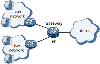
If the PE fails, the hosts connected to it cannot communicate with the external network. This communication failure persists even if another router is added to the LAN. This is because only a single default gateway can be configured for most hosts on a LAN and forward all data packets destined for devices that are not on the local network segment. Hosts send packets only through the default gateway though they are connected to multiple routers.
Configuring multiple egress gateways is a common method to prevent communication interruptions. This method is available only if one of routes to these egress gateways can be selected. Another method is to use dynamic routing protocols, such as the Routing Information Protocol (RIP), Open Shortest Path First (OSPF), and ICMP Router Discovery Protocol (IRDP). This method is available only if every host runs a dynamic routing protocol and there is no problem in management, security, or operating systems' support for protocols.
VRRP prevents communication failures in a better way than the preceding two methods. VRRP is configured only on routers to implement gateway backup, without any networking changes or burden on hosts.
VRRP6 Definition
VRRP6 is an application of VRRP in IPv6 scenarios. VRRP6 allows logical devices to work separately from physical devices, and implements route selection among multiple egress gateways.
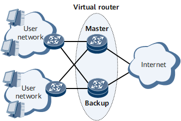
On the network shown in Figure 2, a VRRP6 group is configured on two routers. One is the master and the other is the backup. The two routers form a virtual router and this virtual router is assigned a virtual IPv6 address and a virtual MAC address. Hosts monitor only the presence of the virtual router. The hosts communicate with devices on other network segments through the virtual router.
A virtual router consists of a master router and one or more backup routers. Only the master router forwards packets. If the master router fails, a backup router is elected as the master router through VRRP negotiation and takes over.
On a multicast or broadcast LAN (for example, an Ethernet), VRRP6 uses a logical VRRP6 gateway to ensure reliability for key links. VRRP6 prevents service interruptions if a physical VRRP6 gateway fails, providing high reliability. VRRP6 configuration is simple and takes effect without modification in configurations, such as routing protocol configurations.
Basic VRRP6 Functions
VRRP6 supports two modes: master/backup mode and load balancing mode.
Figure 3 shows the master/backup mode. Figure 4 shows the load balancing mode.
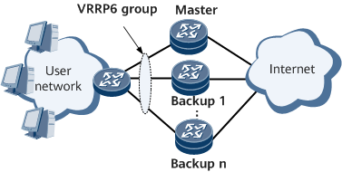
- For the master/backup mode:
- A single VRRP6 group is configured and consists of a master device and several backup devices.
- The router with the highest priority functions as the master device and transmits service packets.
- Other routers function as backup devices and monitor the master device's status. If the master device fails, a backup device with the highest priority preempts the Master state.
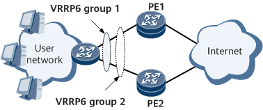
- In load balancing mode, multiple VRRP6 groups can be configured to implement load balancing. A router can belong to multiple VRRP6 groups. On the network shown in Figure 4:
- PE1 is the master device in VRRP6 group 1 and the backup device in VRRP6 group 2.
- PE2 is the master device in VRRP6 group 2 and the backup device in VRRP6 group 1.
- In normal circumstances, different routers process different user groups' traffic to implement load balancing.