Example for Configuring a VRRP Group
In this example, a VRRP group is configured to work in master/backup mode. The master router in the VRRP group transmits all network traffic.
Networking Requirements
Hosts are connected to a network through gateway devices. To ensure non-stop service transmission, configure a VRRP group on the devices.

Interfaces 1 through 3 in this example represent GE 0/1/1, GE 0/1/2, and GE 0/1/8, respectively.
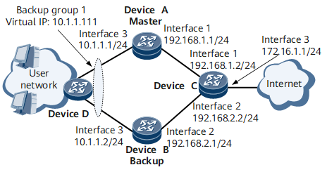
Precautions
The IP address of GE 0/1/8 on Device A and IP address of GE 0/1/8 on Device B must be configured on the same network segment.
Configuration Roadmap
The configuration roadmap is as follows:
- Assign an IP address to each interface on each router and configure a routing protocol to ensure IP reachability.
- Create a VRRP group on Device A and Device B. Configure Device A with a priority greater than that for Device B. This setting allows Device A to function as the master device to transmit traffic and Device B to function as the backup device to provide backup.
Data Preparation
To complete the configuration, you need the following data:
IP address of each interface on each Device and Layer 2 transparent transmission on Device D
- VRID (1) and virtual IP address (10.1.1.111) for a VRRP group configured on Device A and Device B
- VRRP priorities (120 for Device A and 100 for Device B)
- Preemption delay (20s) on Device A
Procedure
- Assign an IP address to each interface on Device A, Device B, and Device C. Configure OSPF to ensure that these routers can communicate with each other. For details about Device D configurations, see Configuration Files in this section.
# Configure Device A.
<HUAWEI> system-view
[~HUAWEI] sysname DeviceA
[*HUAWEI] commit
[~DeviceA] interface gigabitethernet 0/1/8
[~DeviceA-GigabitEthernet0/1/8] undo shutdown
[*DeviceA-GigabitEthernet0/1/8] ip address 10.1.1.1 24
[*DeviceA-GigabitEthernet0/1/8] commit
[~DeviceA-GigabitEthernet0/1/8] quit
[~DeviceA] interface gigabitethernet 0/1/1
[~DeviceA-GigabitEthernet0/1/1] undo shutdown
[*DeviceA-GigabitEthernet0/1/1] ip address 192.168.1.1 24
[*DeviceA-GigabitEthernet0/1/1] commit
[~DeviceA-GigabitEthernet0/1/1] quit
[~DeviceA] ospf 1
[*DeviceA-ospf-1] area 0
[*DeviceA-ospf-1-area-0.0.0.0] network 10.1.1.0 0.0.0.255
[*DeviceA-ospf-1-area-0.0.0.0] network 192.168.1.0 0.0.0.255
[*DeviceA-ospf-1-area-0.0.0.0] commit
[~DeviceA-ospf-1-area-0.0.0.0] quit
[~DeviceA-ospf-1] quit
# Configure Device B.
<HUAWEI> system-view
[~HUAWEI] sysname DeviceB
[*HUAWEI] commit
[~DeviceB] interface gigabitethernet 0/1/8
[~DeviceB-GigabitEthernet0/1/8] undo shutdown
[*DeviceB-GigabitEthernet0/1/8] ip address 10.1.1.2 24
[*DeviceB-GigabitEthernet0/1/8] commit
[~DeviceB-GigabitEthernet0/1/8] quit
[~DeviceB] interface gigabitethernet 0/1/2
[~DeviceB-GigabitEthernet0/1/2] undo shutdown
[*DeviceB-GigabitEthernet0/1/2] ip address 192.168.2.1 24
[*DeviceB-GigabitEthernet0/1/2] commit
[~DeviceB-GigabitEthernet0/1/2] quit
[~DeviceB] ospf 1
[*DeviceB-ospf-1] area 0
[*DeviceB-ospf-1-area-0.0.0.0] network 10.1.1.0 0.0.0.255
[*DeviceB-ospf-1-area-0.0.0.0] network 192.168.2.0 0.0.0.255
[*DeviceB-ospf-1-area-0.0.0.0] commit
[~DeviceB-ospf-1-area-0.0.0.0] quit
[~DeviceB-ospf-1] quit
# Configure Device C.
<HUAWEI> system-view
[~HUAWEI] sysname DeviceC
[*HUAWEI] commit
[~DeviceC] interface gigabitethernet 0/1/1
[~DeviceC-GigabitEthernet0/1/1] undo shutdown
[*DeviceC-GigabitEthernet0/1/1] ip address 192.168.1.2 24
[*DeviceC-GigabitEthernet0/1/1] commit
[~DeviceC-GigabitEthernet0/1/1] quit
[~DeviceC] interface gigabitethernet 0/1/2
[~DeviceC-GigabitEthernet0/1/2] undo shutdown
[*DeviceC-GigabitEthernet0/1/2] ip address 192.168.2.2 24
[*DeviceC-GigabitEthernet0/1/2] commit
[~DeviceC-GigabitEthernet0/1/2] quit
[~DeviceC] interface gigabitethernet 0/1/8
[~DeviceC-GigabitEthernet0/1/8] undo shutdown
[*DeviceC-GigabitEthernet0/1/8] ip address 172.16.1.1 24
[*DeviceC-GigabitEthernet0/1/8] commit
[~DeviceC-GigabitEthernet0/1/8] quit
[~DeviceC] ospf 1
[*DeviceC-ospf-1] area 0
[*DeviceC-ospf-1-area-0.0.0.0] network 192.168.1.0 0.0.0.255
[*DeviceC-ospf-1-area-0.0.0.0] network 192.168.2.0 0.0.0.255
[*DeviceC-ospf-1-area-0.0.0.0] network 172.16.1.0 0.0.0.255
[*DeviceC-ospf-1-area-0.0.0.0] commit
[~DeviceC-ospf-1-area-0.0.0.0] quit
[~DeviceC-ospf-1] quit
- Create a VRRP group.
# Create group 1 on the interface; set the VRRP priority of Device A to 120 so that Device A functions as the master device; set the preemption delay to 20s.
[~DeviceA] interface gigabitethernet 0/1/8
[~DeviceA-GigabitEthernet0/1/8] vrrp vrid 1 virtual-ip 10.1.1.111
[*DeviceA-GigabitEthernet0/1/8] vrrp vrid 1 priority 120
[*DeviceA-GigabitEthernet0/1/8] vrrp vrid 1 preempt-mode timer delay 20
[*DeviceA-GigabitEthernet0/1/8] vrrp recover-delay 20
[*DeviceA-GigabitEthernet0/1/8] commit
[~DeviceA-GigabitEthernet0/1/8] quit
# Create group 1 on the interface.
[~DeviceB] interface gigabitethernet 0/1/8
[~DeviceB-GigabitEthernet0/1/8] vrrp vrid 1 virtual-ip 10.1.1.111
[*DeviceB-GigabitEthernet0/1/8] commit
[~DeviceB-GigabitEthernet0/1/8] quit
- Verify the configuration.
After completing the configurations, run the display vrrp command on Device A and Device B. The command outputs show that Device A's and Device B's VRRP statuses are Master and Backup, respectively.
[~DeviceA] display vrrp
GigabitEthernet0/1/8 | Virtual Router 1
State         : Master
Virtual IP        : 10.1.1.111
Master IP         : 10.1.1.1
Local IP          : 10.1.1.1
PriorityRun       : 120
PriorityConfig    : 120
MasterPriority    : 120
Preempt           : YES      Delay Time : 20s
Hold Multiplier   : 4
TimerRun          : 1s
TimerConfig       : 1s
Auth Type         : NONE
Virtual MAC       : 00e0-fc12-7890
Check TTL         : YES
Config Type       : normal-vrrp
Backup-forward    : disabled
Create Time          : 2011-12-29 05:41:23
Last Change Time     : 2011-12-29 05:41:33
[~DeviceB] display vrrp
GigabitEthernet0/1/8 | Virtual Router 1
State         : Backup
Virtual IP        : 10.1.1.111
Master IP         : 10.1.1.1
Local IP          : 10.1.1.2
PriorityRun       : 100
PriorityConfig    : 100
MasterPriority    : 120
Preempt           : YES      Delay Time : 0s
Hold Multiplier   : 4
TimerRun          : 1s
TimerConfig       : 1s
Auth Type         : NONE
Virtual MAC       : 00e0-fc12-7890
Check TTL         : YES
Config Type       : normal-vrrp
Backup-forward    : disabled
Create Time          : 2011-12-29 05:41:23
Last Change Time    : 2011-12-29 05:41:33
# Run the display ip routing-table command on Device A and Device B. A direct route to the virtual IP address of the VRRP group exists in Device A's routing table and an OSPF route to the virtual IP address of the VRRP group exists in Device B's routing table. The command output on Device A and Device B is as follows:
[~DeviceA] display ip routing-table
Route Flags: R - relay, D - download to fib, T - to vpn-instance, B - black hole route
------------------------------------------------------------------------------
Routing Table : _public_
         Destinations : 14       Routes : 14

Destination/Mask    Proto  Pre  Cost        Flags NextHop         Interface

       10.1.1.0/24  Direct 0    0             D  10.1.1.1        GigabitEthernet0/1/8
       10.1.1.1/32  Direct 0    0             D  127.0.0.1       GigabitEthernet0/1/8
   10.1.1.111/32   Direct 0   0            D  127.0.0.1       GigabitEthernet0/1/8
     10.1.1.255/32  Direct 0    0             D  127.0.0.1       GigabitEthernet0/1/8
       172.16.1.0/24  OSPF   10   2             D  192.168.1.2     GigabitEthernet0/1/1
      127.0.0.0/8   Direct 0    0             D  127.0.0.1       InLoopBack0
      127.0.0.1/32  Direct 0    0             D  127.0.0.1       InLoopBack0
127.255.255.255/32  Direct 0    0             D  127.0.0.1       InLoopBack0
    192.168.1.0/24  Direct 0    0             D  192.168.1.1     GigabitEthernet0/1/1
    192.168.1.1/32  Direct 0    0             D  127.0.0.1       GigabitEthernet0/1/1
    192.168.1.2/32  Direct 0    0             D  192.168.1.2     GigabitEthernet0/1/1
  192.168.1.255/32  Direct 0    0             D  127.0.0.1       GigabitEthernet0/1/1
    192.168.2.0/24  OSPF   10   2             D  10.1.1.2        GigabitEthernet0/1/8
255.255.255.255/32  Direct 0    0             D  127.0.0.1       InLoopBack0
[~DeviceB] display ip routing-table
Route Flags: R - relay, D - download to fib, T - to vpn-instance, B - black hole route
------------------------------------------------------------------------------
Routing Table : _public_
         Destinations : 13       Routes : 13

Destination/Mask    Proto  Pre  Cost        Flags NextHop         Interface

       10.1.1.0/24  Direct 0    0             D  10.1.1.2        GigabitEthernet0/1/8
       10.1.1.2/32  Direct 0    0             D  127.0.0.1       GigabitEthernet0/1/8
   10.1.1.111/32   OSPF   10  2             D  10.1.1.1        GigabitEthernet0/1/8
     10.1.1.255/32  Direct 0    0             D  127.0.0.1       GigabitEthernet0/1/8
     172.16.1.0/24  OSPF   10   2             D  192.168.2.2     GigabitEthernet0/1/2
      127.0.0.0/8   Direct 0    0             D  127.0.0.1       InLoopBack0
      127.0.0.1/32  Direct 0    0             D  127.0.0.1       InLoopBack0
127.255.255.255/32  Direct 0    0             D  127.0.0.1       InLoopBack0
    192.168.1.0/24  OSPF   10   2             D  10.1.1.1        GigabitEthernet0/1/8
    192.168.2.0/32  Direct 0    0             D  127.0.0.1       GigabitEthernet0/1/2
    192.168.2.1/32  Direct 0    0             D  192.168.2.1     GigabitEthernet0/1/2
    192.168.2.2/24  Direct 0    0             D  127.0.0.1       GigabitEthernet0/1/2
  192.168.2.255/32  Direct 0    0             D  127.0.0.1       GigabitEthernet0/1/2
255.255.255.255/32  Direct 0    0             D  127.0.0.1       InLoopBack0
Verify that Device B becomes the master device after Device A fails.
Run the shutdown command on GE 0/1/8 of Device A to simulate a failure in Device A.
Run the display vrrp command on Device A and Device B. The command outputs show that Device A's and Device B's VRRP statuses are Initialize and Master, respectively.
[~DeviceA] display vrrp
GigabitEthernet0/1/8 | Virtual Router 1
State         : Initialize
Virtual IP        : 10.1.1.111
Master IP         : 0.0.0.0
Local IP          : 10.1.1.1
PriorityRun       : 120
PriorityConfig    : 120
MasterPriority    : 0
Preempt           : YES      Delay Time : 20s
Hold Multiplier   : 4
TimerRun          : 1s
TimerConfig       : 1s
Auth Type         : NONE
Virtual MAC       : 00e0-fc12-7890
Check TTL         : YES
Config Type       : normal-vrrp
Backup-forward    : disabled
Create Time          : 2011-12-29 05:51:23
Last Change Time     : 2011-12-29 05:51:33
[~DeviceB] display vrrp
GigabitEthernet0/1/8 | Virtual Router 1
State         : Master
Virtual IP        : 10.1.1.111
Master IP         : 10.1.1.2
Local IP          : 10.1.1.2
PriorityRun       : 100
PriorityConfig    : 100
MasterPriority    : 100
Preempt           : YES      Delay Time : 0s
Hold Multiplier   : 4
TimerRun          : 1s
TimerConfig       : 1s
Auth Type         : NONE
Virtual MAC       : 00e0-fc12-7890
Check TTL         : YES
Config Type       : normal-vrrp
Backup-forward    : disabled
Create Time          : 2011-12-29 05:51:23
Last Change Time     : 2011-12-29 05:51:33
Verify that Device A can preempt the Master state after recovering.
Run the undo shutdown command on GE 0/1/8 of Device A. After GE 0/1/8 goes Up, wait 20 seconds and run the display vrrp command on Device A and Device B. The command outputs show that Device A's and Device B's VRRP statuses are Master and Backup, respectively.
[~DeviceA] display vrrp
GigabitEthernet0/1/8 | Virtual Router 1
State         : Master
Virtual IP        : 10.1.1.111
Master IP         : 10.1.1.1
Local IP          : 10.1.1.1
PriorityRun       : 120
PriorityConfig    : 120
MasterPriority    : 120
Preempt           : YES      Delay Time : 20s
Hold Multiplier   : 4
TimerRun          : 1s
TimerConfig       : 1s
Auth Type         : NONE
Virtual MAC       : 00e0-fc12-7890
Check TTL         : YES
Config Type       : normal-vrrp
Backup-forward    : disabled
Create Time          : 2011-12-29 05:56:23
Last Change Time     : 2011-12-29 05:56:33
[~DeviceB] display vrrp
GigabitEthernet0/1/8 | Virtual Router 1
State         : Backup
Virtual IP        : 10.1.1.111
Master IP         : 10.1.1.1
Local IP          : 10.1.1.2
PriorityRun       : 100
PriorityConfig    : 100
MasterPriority    : 120
Preempt           : YES      Delay Time : 0s
Hold Multiplier   : 4
TimerRun          : 1s
TimerConfig       : 1s
Auth Type         : NONE
Virtual MAC       : 00e0-fc12-7890
Check TTL         : YES
Config Type       : normal-vrrp
Backup-forward    : disabled
Create Time          : 2011-12-29 05:56:23
Last Change Time     : 2011-12-29 05:56:33
Configuration Files
Device A configuration file
#
 sysname DeviceA
#
interface GigabitEthernet0/1/1
 undo shutdown
 ip address 192.168.1.1 255.255.255.0
#
interface GigabitEthernet0/1/8
 undo shutdown
 ip address 10.1.1.1 255.255.255.0
 vrrp vrid 1 virtual-ip 10.1.1.111
 vrrp vrid 1 priority 120
 vrrp vrid 1 preempt-mode timer delay 20
 vrrp recover-delay 20
#
ospf 1
 area 0.0.0.0
  network 192.168.1.0 0.0.0.255
  network 10.1.1.0 0.0.0.255
#
return
Device B configuration file
#
 sysname DeviceB
#
interface GigabitEthernet0/1/2
 undo shutdown
 ip address 192.168.2.1 255.255.255.0
#
interface GigabitEthernet0/1/8
 undo shutdown
 ip address 10.1.1.2 255.255.255.0
 vrrp vrid 1 virtual-ip 10.1.1.111
#
ospf 1
 area 0.0.0.0
  network 192.168.2.0 0.0.0.255
  network 10.1.1.0 0.0.0.255
#
return
Device C configuration file
#
 sysname DeviceC
#
interface GigabitEthernet0/1/1
 undo shutdown
 ip address 192.168.1.2 255.255.255.0
#
interface GigabitEthernet0/1/2
 undo shutdown
 ip address 192.168.2.2 255.255.255.0
#
interface GigabitEthernet0/1/8
 undo shutdown
 ip address 172.16.1.1 255.255.255.0
#
ospf 1
 area 0.0.0.0
  network 192.168.1.0 0.0.0.255
  network 192.168.2.0 0.0.0.255
  network 172.16.1.0 0.0.0.255
#
return
Device D configuration file
#
 sysname DeviceD
#
 vlan 10
#
interface GigabitEthernet0/1/1
 undo shutdown
 portswitch
 port default vlan 10
#
interface GigabitEthernet0/1/2
 undo shutdown
 portswitch
 port default vlan 10
#
return