Example for Configuring an mVRRP Group
In this example, an mVRRP group is configured to determine the master/backup status of service VRRP groups bound to it.
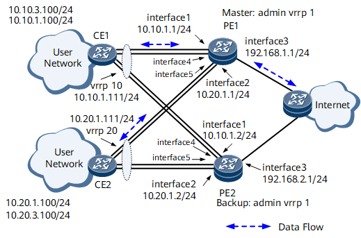
Networking Requirements

Interfaces 1 through 5 in this example represent GE 0/1/1, GE 0/1/2, GE 0/1/3, GE 0/1/4, and GE 0/1/5, respectively.
Configuration Roadmap
The configuration roadmap is as follows:
- Assign an IP address to each interface on each PE, configure a routing protocol to ensure IP connectivity on each PE, and configure Layer 2 transparent transmission on CE1 and CE2.
- Create an mVRRP group on each PE.
- Create a VRRP group on each interface connecting a PE to a CE and bind the VRRP groups to the mVRRP group.
Procedure
- Assign an IP address to each interface on each PE and configure OSPF. For details about CE configurations, see Configuration Files in this section.
# Configure PE1.
[~PE1] interface gigabitethernet0/1/1
[~PE1-GigabitEthernet0/1/1] undo shutdown
[*PE1-GigabitEthernet0/1/1] ip address 10.10.1.1 24
[*PE1-GigabitEthernet0/1/1] commit
[~PE1-GigabitEthernet0/1/1] quit
[~PE1] interface gigabitethernet0/1/2
[~PE1-GigabitEthernet0/1/2] undo shutdown
[*PE1-GigabitEthernet0/1/2] ip address 10.20.1.1 24
[*PE1-GigabitEthernet0/1/2] commit
[~PE1-GigabitEthernet0/1/2] quit
[~PE1] interface gigabitethernet0/1/3
[~PE1-GigabitEthernet0/1/3] undo shutdown
[*PE1-GigabitEthernet0/1/3] ip address 192.168.1.1 24
[*PE1-GigabitEthernet0/1/3] commit
[~PE1-GigabitEthernet0/1/3] quit
[~PE1] interface gigabitethernet0/1/4
[~PE1-GigabitEthernet0/1/4] undo shutdown
[*PE1-GigabitEthernet0/1/4] ip address 10.10.3.1 24
[*PE1-GigabitEthernet0/1/4] commit
[~PE1-GigabitEthernet0/1/4] quit
[~PE1] interface gigabitethernet0/1/5
[~PE1-GigabitEthernet0/1/5] undo shutdown
[*PE1-GigabitEthernet0/1/5] ip address 10.20.3.1 24
[*PE1-GigabitEthernet0/1/5] commit
[~PE1-GigabitEthernet0/1/5] quit
[~PE1] ospf
[*PE1-ospf-1] area 0
[*PE1-ospf-1-area-0.0.0.0] network 10.10.1.0 0.0.0.255
[*PE1-ospf-1-area-0.0.0.0] network 10.10.3.0 0.0.0.255
[*PE1-ospf-1-area-0.0.0.0] network 10.20.1.0 0.0.0.255
[*PE1-ospf-1-area-0.0.0.0] network 10.20.3.0 0.0.0.255
[*PE1-ospf-1-area-0.0.0.0] network 192.168.1.0 0.0.0.255
[*PE1-ospf-1-area-0.0.0.0] commit
[~PE1-ospf-1-area-0.0.0.0] quit
[~PE1-ospf-1] quit
# Configure PE2.
[~PE2] interface gigabitethernet0/1/1
[~PE2-GigabitEthernet0/1/1] undo shutdown
[*PE2-GigabitEthernet0/1/1] ip address 10.10.1.2 24
[*PE2-GigabitEthernet0/1/1] commit
[~PE2-GigabitEthernet0/1/1] quit
[~PE2] interface gigabitethernet0/1/2
[~PE2-GigabitEthernet0/1/2] undo shutdown
[*PE2-GigabitEthernet0/1/2] ip address 10.20.1.2 24
[*PE2-GigabitEthernet0/1/2] commit
[~PE2-GigabitEthernet0/1/2] quit
[~PE2] interface gigabitethernet0/1/3
[~PE2-GigabitEthernet0/1/3] undo shutdown
[*PE2-GigabitEthernet0/1/3] ip address 192.168.2.1 24
[*PE2-GigabitEthernet0/1/3] commit
[~PE2-GigabitEthernet0/1/3] quit
[~PE2] interface gigabitethernet0/1/4
[*PE2-GigabitEthernet0/1/4] ip address 10.10.3.2 24
[*PE2-GigabitEthernet0/1/4] commit
[~PE2-GigabitEthernet0/1/4] quit
[~PE2] interface gigabitethernet0/1/5
[*PE2--GigabitEthernet0/1/5] ip address 10.20.3.2 24
[*PE2--GigabitEthernet0/1/5] commit
[~PE2--GigabitEthernet0/1/5] quit
[~PE2] ospf
[*PE2-ospf-1] area 0
[*PE2-ospf-1-area-0.0.0.0] network 10.10.1.0 0.0.0.255
[*PE2-ospf-1-area-0.0.0.0] network 10.10.3.0 0.0.0.255
[*PE2-ospf-1-area-0.0.0.0] network 10.20.1.0 0.0.0.255
[*PE2-ospf-1-area-0.0.0.0] network 10.20.3.0 0.0.0.255
[*PE2-ospf-1-area-0.0.0.0] network 192.168.2.0 0.0.0.255
[*PE2-ospf-1-area-0.0.0.0] commit
[~PE2-ospf-1-area-0.0.0.0] quit
[~PE2-ospf-1]quit
- Configure an mVRRP group on the interface of each PE and set a higher VRRP priority for PE1.
# Configure PE1.
[~PE1] interface gigabitethernet0/1/4
[*PE1-GigabitEthernet0/1/4] vrrp vrid 1 virtual-ip 10.10.3.111
[*PE1-GigabitEthernet0/1/4] admin-vrrp vrid 1
[*PE1-GigabitEthernet0/1/4] vrrp vrid 1 priority 120
[*PE1-GigabitEthernet0/1/4] commit
[~PE1-GigabitEthernet0/1/4] quit
[~PE1] interface gigabitethernet0/1/5
[*PE1-GigabitEthernet0/1/5] vrrp vrid 2 virtual-ip 10.20.3.111
[*PE1-GigabitEthernet0/1/5] admin-vrrp vrid 2
[*PE1-GigabitEthernet0/1/5] vrrp vrid 2 priority 120
[*PE1-GigabitEthernet0/1/5] commit
[~PE1-GigabitEthernet0/1/5] quit
# Configure PE2.
[~PE2] interface GigabitEthernet0/1/4
[*PE2-GigabitEthernet0/1/4] vrrp vrid 1 virtual-ip 10.10.3.111
[*PE2-GigabitEthernet0/1/4] admin-vrrp vrid 1
[*PE2-GigabitEthernet0/1/4] commit
[~PE2-GigabitEthernet0/1/4] quit
[~PE2] interface gigabitethernet0/1/5
[*PE2-GigabitEthernet0/1/5] vrrp vrid 2 virtual-ip 10.20.3.111
[*PE2-GigabitEthernet0/1/5] admin-vrrp vrid 2
[*PE2-GigabitEthernet0/1/5] commit
[~PE2-GigabitEthernet0/1/5] quit
- Create a VRRP group on the interface connecting each PE to the CE and bind the VRRP groups to the mVRRP group, allowing the mVRRP group to determine the master/backup status of these service VRRP groups.
# Configure PE1.
[~PE1] interface gigabitethernet0/1/1
[~PE1-GigabitEthernet0/1/1] vrrp vrid 10 virtual-ip 10.10.1.111
[*PE1-GigabitEthernet0/1/1] vrrp vrid 10 track admin-vrrp interface gigabitethernet0/1/4 vrid 1 unflowdown
[*PE1-GigabitEthernet0/1/1] commit
[~PE1-GigabitEthernet0/1/1] quit
[~PE1] interface gigabitethernet0/1/2
[~PE1-GigabitEthernet0/1/2] vrrp vrid 20 virtual-ip 10.20.1.111
[*PE1-GigabitEthernet0/1/2] vrrp vrid 20 track admin-vrrp interface gigabitethernet0/1/5 vrid 2 unflowdown
[*PE1-GigabitEthernet0/1/2] commit
[~PE1-GigabitEthernet0/1/2] quit
# Configure PE2.
[~PE2] interface gigabitethernet0/1/1
[~PE2-GigabitEthernet0/1/1] vrrp vrid 10 virtual-ip 10.10.1.111
[*PE2-GigabitEthernet0/1/1] vrrp vrid 10 track admin-vrrp interface gigabitethernet0/1/4 vrid 1 unflowdown
[*PE2-GigabitEthernet0/1/1] commit
[~PE2-GigabitEthernet0/1/1] quit
[~PE2] interface gigabitethernet0/1/2
[~PE2-GigabitEthernet0/1/2] vrrp vrid 20 virtual-ip 10.20.1.111
[*PE2-GigabitEthernet0/1/2] vrrp vrid 20 track admin-vrrp interface gigabitethernet0/1/5 vrid 2 unflowdown
[*PE2-GigabitEthernet0/1/2] commit
[~PE2-GigabitEthernet0/1/2] quit
- Verify the configuration.
After completing the configurations, run the display vrrp brief command on each PE.
The command output on PE1 is as follows:In mVRRP group 1 and 2, the value of the State field is Master and the value of the Type field is Admin.
In each service VRRP group, the value of the State field is Master and the value of the Type field is Member.
[~PE1] display vrrp brief
Total:3     Master:3    Backup:0    Non-active:0
VRID   State       Interface        Type    Virtual IP
--------------------------------------------------------
1     Master      GE0/1/4          Admin   10.10.3.111
2     Master      GE0/1/5          Admin   10.20.3.111
10    Master      GE0/1/1          Member  10.10.1.111
20    Master      GE0/1/2          Member  10.20.1.111
The command output on PE2 is as follows:In mVRRP group 1 and 2, the value of the State field is Backup and the value of the Type field is Admin.
In each service VRRP group, the value of the State field is Backup and the value of the Type field is Member.
[~PE2] display vrrp brief
Total:3     Master:0    Backup:3    Non-active:0
VRID   State       Interface        Type    Virtual IP
--------------------------------------------------------
1     Backup      GE0/1/4          Admin   10.10.3.111
2     Backup      GE0/1/5          Admin   10.20.3.111
10    Backup      GE0/1/1          Member  10.10.1.111
20    Backup      GE0/1/2          Member  10.20.1.111
Run the shutdown command on GE 0/1/1, GE 0/1/2, GE 0/1/4, and GE 0/1/5 of PE1 to simulate a device fault.
Then the mVRRP group performs a master/backup VRRP switchover. Run the display vrrp command on each PE.
The command output on PE1 is as follows:In mVRRP group 1 and 2, the value of the State field is Initialize and the value of the Type field is Admin.
In each service VRRP group, the value of the State field is Initialize and the value of the Type field is Member.
[~PE1] display vrrp brief
Total:3     Master:0    Backup:0    Non-active:3
VRID   State       Interface         Type    Virtual IP
--------------------------------------------------------
1     Initialize  GE0/1/4           Admin   10.10.3.111
2     Initialize  GE0/1/5           Admin   10.20.3.111
10    Initialize  GE0/1/1           Member  10.10.1.111
20    Initialize  GE0/1/2           Member  10.20.1.111
The command output on PE2 is as follows:In mVRRP group 1 and 2, the value of the State field is Master and the value of the Type field is Admin.
In each service VRRP group, the value of the State field is Master and the value of the Type field is Member.
[~PE2] display vrrp brief
Total:3     Master:3    Backup:0    Non-active:0
VRID   State       Interface         Type    Virtual IP
--------------------------------------------------------
1     Master      GE0/1/4           Admin   10.10.3.111
2     Master      GE0/1/5           Admin   10.20.3.111
10    Master      GE0/1/1           Member  10.10.1.111
20    Master      GE0/1/2           Member  10.20.1.111
Run the undo shutdown command on GE 0/1/1, GE 0/1/2, GE 0/1/4, and GE 0/1/5 of PE1 to restore PE1.
A VRRP switchback is performed and the VRRP status of each PE in each VRRP group is restored. Run the display vrrp command on each PE.
The command output on PE1 is as follows:In mVRRP group 1 and 2, the value of the State field is Master and the value of the Type field is Admin.
In each service VRRP group, the value of the State field is Master and the value of the Type field is Member.
[~PE1] display vrrp brief
Total:3     Master:3    Backup:0    Non-active:0
VRID   State       Interface        Type    Virtual IP
--------------------------------------------------------
1     Master      GE0/1/4          Admin   10.10.3.111
1     Master      GE0/1/5          Admin   10.20.3.111
10    Master      GE0/1/1          Member  10.10.1.111
20    Master      GE0/1/2          Member  10.20.1.111
The command output on PE2 is as follows:In mVRRP group 1 and 2, the value of the State field is Backup and the value of the Type field is Admin.
In each service VRRP group, the value of the State field is Backup and the value of the Type field is Member.
[~PE2] display vrrp brief
Total:3     Master:0    Backup:3    Non-active:0
VRID   State       Interface        Type    Virtual IP
--------------------------------------------------------
1     Backup      GE0/1/4          Admin   10.10.3.111
1     Backup      GE0/1/5          Admin   10.20.3.111
10    Backup      GE0/1/1          Member  10.10.1.111
20    Backup      GE0/1/2          Member  10.20.1.111
Configuration Files
PE1 configuration file
#
 sysname PE1
#
interface GigabitEthernet0/1/1
 undo shutdown
 ip address 10.10.1.1 255.255.255.0
 vrrp vrid 10 virtual-ip 10.10.1.111
 vrrp vrid 10 track admin-vrrp interface gigabitethernet0/1/4 vrid 1 unflowdown
#
interface GigabitEthernet0/1/2
 undo shutdown
 ip address 10.20.1.1 255.255.255.0
 vrrp vrid 20 virtual-ip 10.20.1.111
 vrrp vrid 20 track admin-vrrp interface gigabitethernet0/1/5 vrid 2 unflowdown
#
interface GigabitEthernet0/1/3
 undo shutdown
 ip address 192.168.1.1 255.255.255.0
#
interface GigabitEthernet0/1/4
 undo shutdown
 ip address 10.10.3.1 255.255.255.0
 vrrp vrid 1 virtual-ip 10.10.3.111
 admin-vrrp vrid 1
 vrrp vrid 1 priority 120
#
interface GigabitEthernet0/1/5
 undo shutdown
 ip address 10.20.3.1 255.255.255.0
 vrrp vrid 2 virtual-ip 10.20.3.111
 admin-vrrp vrid 2
 vrrp vrid 2 priority 120
#
ospf 1
 area 0.0.0.0
  network 10.10.1.0 0.0.0.255
  network 10.10.3.0 0.0.0.255
  network 10.20.1.0 0.0.0.255
  network 10.20.3.0 0.0.0.255
  network 192.168.1.0 0.0.0.255
#
return
PE2 configuration file
#
 sysname PE2
#
interface GigabitEthernet0/1/1
 undo shutdown
 ip address 10.10.1.1 255.255.255.0
 vrrp vrid 10 virtual-ip 10.10.1.111
 vrrp vrid 10 track admin-vrrp interface gigabitethernet0/1/4 vrid 1 unflowdown
#
interface GigabitEthernet0/1/2
 undo shutdown
 ip address 10.20.1.1 255.255.255.0
 vrrp vrid 20 virtual-ip 10.20.1.111
 vrrp vrid 20 track admin-vrrp interface gigabitethernet0/1/5 vrid 2 unflowdown
#
interface GigabitEthernet0/1/3
 undo shutdown
 ip address 192.168.2.1 255.255.255.0
#
interface GigabitEthernet0/1/4
 ip address 10.10.3.2 255.255.255.0
 vrrp vrid 1 virtual-ip 10.10.3.111
 admin-vrrp vrid 1
#
interface GigabitEthernet0/1/5
 ip address 10.20.3.2 255.255.255.0
 vrrp vrid 2 virtual-ip 10.20.3.111
 admin-vrrp vrid 2
#
ospf 1
 area 0.0.0.0
  network 10.10.1.0 0.0.0.255
  network 10.10.3.0 0.0.0.255
  network 10.20.1.0 0.0.0.255
  network 10.20.3.0 0.0.0.255
  network 192.168.2.0 0.0.0.255
#
return
CE1 configuration file
#
 sysname CE1
#
 vlan batch 10 20
#
interface GigabitEthernet0/1/1
 undo shutdown
 port default vlan 10
#
interface gigabitethernet0/1/2
 undo shutdown
 port default vlan 10
#
interface gigabitethernet0/1/3
 undo shutdown
 port default vlan 20
#
interface gigabitethernet0/1/4
 undo shutdown
 port default vlan 20
#
return
CE2 configuration file
#
 sysname CE2
#
 vlan batch 10 20
#
interface GigabitEthernet0/1/1
 undo shutdown
 portswitch
 port default vlan 10
#
interface gigabitethernet0/1/2
 undo shutdown
 port default vlan 10
#
interface gigabitethernet0/1/3
 undo shutdown
 portswitch
 port default vlan 20
#
interface gigabitethernet0/1/4
 undo shutdown
 portswitch
 port default vlan 20
#
return