Example for Configuring Users on the Same Network Segment to Communicate Through a VXLAN Tunnel
This section provides an example for configuring users on the same network segment to communicate through a VXLAN tunnel.
Networking Requirements
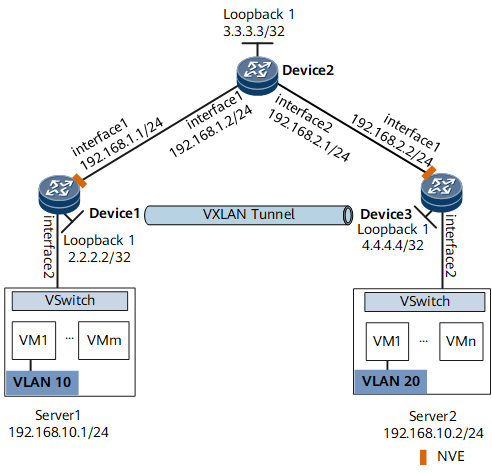
On the network shown in Figure 1, an enterprise has VMs deployed in different data centers. VM1 on Server1 belongs to VLAN10, and VM1 on Server2 belongs to VLAN20. VM1 on Server1 and VM1 on Server2 reside on the same network segment. To allow VM1s in different data centers to communicate with each other, configure a VXLAN tunnel between Device1 and Device3.

Configuration Roadmap
- Configure a routing protocol on Device1, Device2, and Device3 to allow them to communicate at Layer 3.
- Configure a service access point on Device1 and Device3 to differentiate service traffic.
- Configure a VXLAN tunnel on Device1 and Device3 to forward service traffic.
Data Preparation
To complete the configuration, you need the following data:
- VMs' VLAN IDs (10 and 20)
- IP addresses of interfaces connecting devices
- Interior Gateway Protocol (IGP) running between devices (OSPF in this example)
- BD ID (10)
- VNI ID (5010)
Procedure
- Configure a routing protocol.
Assign an IP address to each interface on Device1, Device2, and Device3 according to Figure 1.
# Configure Device1.<HUAWEI> system-view [~HUAWEI] sysname Device1 [*HUAWEI] commit [~Device1] interface loopback 1 [*Device1-LoopBack1] ip address 2.2.2.2 32 [*Device1-LoopBack1] quit [*Device1] interface gigabitethernet 0/1/1 [*Device1-GigabitEthernet0/1/1] ip address 192.168.1.1 24 [*Device1-GigabitEthernet0/1/1] quit [*Device1] ospf [*Device1-ospf-1] area 0 [*Device1-ospf-1-area-0.0.0.0] network 2.2.2.2 0.0.0.0 [*Device1-ospf-1-area-0.0.0.0] network 192.168.1.0 0.0.0.255 [*Device1-ospf-1-area-0.0.0.0] quit [*Device1-ospf-1] quit [*Device1] commit
Repeat these steps for Device2 and Device3. For configuration details, see Configuration Files in this section.
After OSPF is configured, the devices can use OSPF to learn the IP addresses of loopback interfaces of each other and successfully ping each other. The following example shows the command output on Device1 after it pings Device3:[~Device1] ping 4.4.4.4 PING 4.4.4.4: 56 data bytes, press CTRL_C to break Reply from 4.4.4.4: bytes=56 Sequence=1 ttl=254 time=5 ms Reply from 4.4.4.4: bytes=56 Sequence=2 ttl=254 time=2 ms Reply from 4.4.4.4: bytes=56 Sequence=3 ttl=254 time=2 ms Reply from 4.4.4.4: bytes=56 Sequence=4 ttl=254 time=3 ms Reply from 4.4.4.4: bytes=56 Sequence=5 ttl=254 time=3 ms --- 4.4.4.4 ping statistics --- 5 packet(s) transmitted 5 packet(s) received 0.00% packet loss round-trip min/avg/max = 2/3/5 ms - Configure a service access point on Device1 and Device3.# Configure Device1.
[~Device1] bridge-domain 10
[*Device1-bd10] quit
[*Device1] interface gigabitethernet0/1/2.1 mode l2
[*Device1-GigabitEthernet0/1/2.1] encapsulation dot1q vid 10
[*Device1-GigabitEthernet0/1/2.1] rewrite pop single
[*Device1-GigabitEthernet0/1/2.1] bridge-domain 10
[*Device1-GigabitEthernet0/1/2.1] quit
[*Device1] commit
Repeat these steps for Device3. For configuration details, see Configuration Files in this section.
- Configure a VXLAN tunnel on Device1 and Device3.# Configure Device1.
[~Device1] bridge-domain 10
[~Device1-bd10] vxlan vni 5010
[*Device1-bd10] quit
[*Device1] interface nve 1
[*Device1-Nve1] source 2.2.2.2
[*Device1-Nve1] vni 5010 head-end peer-list 4.4.4.4
[*Device1-Nve1] quit
[*Device1] commit
Repeat these steps for Device3. For configuration details, see Configuration Files in this section.
- Verify the configuration.
After completing the configurations, run the display vxlan vni and display vxlan tunnel commands on Device1 and Device3 to check the VNI status and VXLAN tunnel information, respectively. The VNIs are Up on Device1 and Device3. The following example shows the command output on Device1.
[~Device1] display vxlan vni
Number of vxlan vni: 1
VNI            BD-ID            State
---------------------------------------
5010           10               up
[~Device1] display vxlan tunnel
Number of vxlan tunnel : 1
Tunnel ID   Source           Destination      State  Type    Uptime
-------------------------------------------------------------------
4026531842  2.2.2.2          4.4.4.4          up     static 0028h16m
By now, users on the same network can communicate through the VXLAN tunnel.
Configuration Files
Device1 configuration file
#
sysname Device1
#
bridge-domain 10
 vxlan vni 5010
#
interface GigabitEthernet0/1/1
 undo shutdown
 ip address 192.168.1.1 255.255.255.0
#
interface GigabitEthernet0/1/2
 undo shutdown
#
interface GigabitEthernet0/1/2.1 mode l2
 encapsulation dot1q vid 10
 rewrite pop single
 bridge-domain 10
#
interface LoopBack1
 ip address 2.2.2.2 255.255.255.255
#
interface Nve1
 source 2.2.2.2
 vni 5010 head-end peer-list 4.4.4.4
#
ospf 1
 area 0.0.0.0
  network 2.2.2.2 0.0.0.0
  network 192.168.1.0 0.0.0.255
#
return
Device2 configuration file
#
sysname Device2
#
interface GigabitEthernet0/1/1
 undo shutdown
 ip address 192.168.1.2 255.255.255.0
#
interface GigabitEthernet0/1/2
 undo shutdown
 ip address 192.168.2.1 255.255.255.0
#
interface LoopBack1
 ip address 3.3.3.3 255.255.255.255
#
ospf 1
 area 0.0.0.0
  network 3.3.3.3 0.0.0.0
  network 192.168.1.0 0.0.0.255
  network 192.168.2.0 0.0.0.255
#
return
Device3 configuration file
#
sysname Device3
#
bridge-domain 10
 vxlan vni 5010
#
interface GigabitEthernet0/1/1
 undo shutdown
 ip address 192.168.2.2 255.255.255.0
#
interface GigabitEthernet0/1/2
 undo shutdown
#
interface GigabitEthernet0/1/2.1 mode l2
 encapsulation dot1q vid 20
 rewrite pop single
 bridge-domain 10
#
interface LoopBack1
 ip address 4.4.4.4 255.255.255.255
#
interface Nve1
 source 4.4.4.4
 vni 5010 head-end peer-list 2.2.2.2
#
ospf 1
 area 0.0.0.0
  network 4.4.4.4 0.0.0.0
  network 192.168.2.0 0.0.0.255
#
return