Overview of VXLAN
VXLAN allows a virtual network to provide access services to a large number of tenants. In addition, tenants are able to plan their own virtual networks, not limited by the physical network IP addresses or broadcast domains. This greatly simplifies network management.
Background
VM scale is limited by network specifications.
On a large Layer 2 network, data packets are forwarded at Layer 2 based on MAC entries. However, the MAC table capacity is limited, which subsequently limits the number of VMs.
Network isolation capabilities are limited.
Most networks currently use VLANs to implement network isolation. However, the deployment of VLANs on large-scale virtualized networks has the following limitations:- The VLAN tag field defined in IEEE 802.1Q has only 12 bits and can support only a maximum of 4094 VLANs, which cannot meet user identification requirements of large Layer 2 networks.
- VLANs on legacy Layer 2 networks cannot adapt to dynamic network adjustment.
VM migration scope is limited by the network architecture.
A running VM may need to be migrated to a new server due to resource issues on the original server (for example, migration may be required if the CPU usage is too high, or memory resources are inadequate). To ensure service continuity during VM migration, the IP address of the VM must remain unchanged. Therefore, the service network must be a Layer 2 network and provide multipathing redundancy backup and reliability.
VXLAN addresses the preceding problems on large Layer 2 networks.
Eliminates VM scale limitations imposed by network specifications.
VXLAN encapsulates data packets sent from VMs into UDP packets and encapsulates IP and MAC addresses used on the physical network into the outer headers. As a result, the network is aware of only the encapsulated parameters and not the inner data. This implementation greatly reduces the MAC address specification requirements of large Layer 2 networks.
Provides greater network isolation capabilities.
VXLAN uses a 24-bit network segment ID, called a VXLAN network identifier (VNI), to identify users. This VNI is similar to a VLAN ID, but supports a maximum of 16M VXLAN segments.
Eliminates VM migration scope limitations imposed by network architecture.
VXLAN uses MAC-in-UDP encapsulation to extend Layer 2 networks. It encapsulates Ethernet packets into IP packets for these Ethernet packets to be transmitted over routes, and does not need to be aware of VMs' MAC addresses. Because there is no limitation on Layer 3 network architecture, Layer 3 networks are scalable and have strong automatic fault rectification and load balancing capabilities. This allows for VM migration irrespective of the network architecture.
Related Concepts
VXLAN allows a virtual network to provide access services to a large number of tenants. In addition, tenants are able to plan their own virtual networks, not limited by the physical network IP addresses or broadcast domains. This greatly simplifies network management. Table 1 describes VXLAN concepts.
Concept |
Description |
|---|---|
Underlay and overlay networks |
VXLAN allows virtual Layer 2 or Layer 3 networks (overlay networks) to be built over existing physical networks (underlay networks). Overlay networks use encapsulation technologies to transmit tenant packets between sites over Layer 3 forwarding paths provided by underlay networks. Tenants are aware of only overlay networks. |
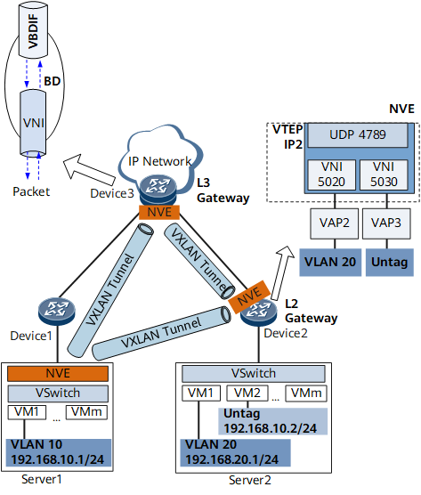
Network virtualization edge (NVE) |
A network entity that is deployed at the network edge and implements network virtualization functions. NOTE:
vSwitches on devices and servers can function as NVEs. |
VXLAN tunnel endpoint (VTEP) |
A VXLAN tunnel endpoint that encapsulates and decapsulates VXLAN packets. It is represented by an NVE. A VTEP connects to a physical network and is assigned a physical network IP address. This IP address is irrelevant to virtual networks. In VXLAN packets, the source IP address is the local node's VTEP address, and the destination IP address is the remote node's VTEP address. This pair of VTEP addresses corresponds to a VXLAN tunnel. |
VXLAN network identifier (VNI) |
A VXLAN segment identifier similar to a VLAN ID. VMs on different VXLAN segments cannot communicate directly at Layer 2. A VNI identifies only one tenant. Even if multiple terminal users belong to the same VNI, they are considered one tenant. A VNI consists of 24 bits and supports a maximum of 16M tenants. A VNI can be a Layer 2 or Layer 3 VNI.
|
Bridge domain (BD) |
A Layer 2 broadcast domain through which VXLAN data packets are forwarded. VNIs identifying VNs must be mapped to BDs so that a BD can function as a VXLAN network entity to transmit VXLAN traffic. |
VBDIF interface |
A Layer 3 logical interface created for a BD. Configuring IP addresses for VBDIF interfaces allows communication between VXLANs on different network segments and between VXLANs and non-VXLANs and implements Layer 2 network access to a Layer 3 network. |
Gateway |
A device that ensures communication between VXLANs identified by different VNIs and between VXLANs and non-VXLANs. A VXLAN gateway can be a Layer 2 or Layer 3 gateway.
|
NVE Deployment Mode
On VXLANs, VTEPs are represented by NVEs, and therefore VXLAN tunnels can be established after NVEs are deployed. The following NVE deployment modes are available where NVEs are deployed.
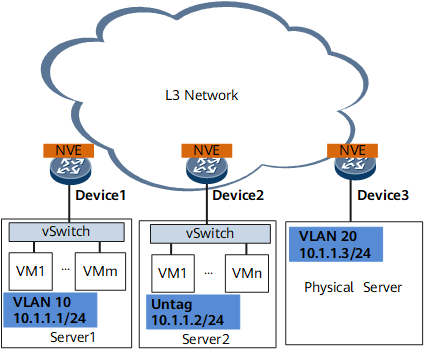
Hardware mode: On the network shown in Figure 2, all NVEs are deployed on NVE-capable devices, which perform VXLAN encapsulation and decapsulation.
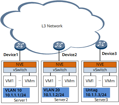
Software mode: On the network shown in Figure 3, all NVEs are deployed on vSwitches, which perform VXLAN encapsulation and decapsulation.
Hybrid mode: On the network shown in Figure 4, some NVEs are deployed on vSwitches, and others on NVE-capable devices. Both vSwitches and NVE-capable devices may perform VXLAN encapsulation and decapsulation.
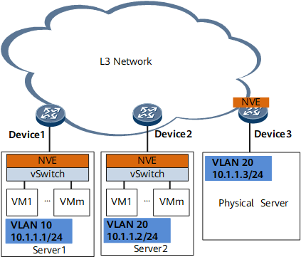

This document describes how to configure VXLAN when NVEs are deployed on NVE-capable devices. If software mode is used, devices only need to transparently transmit VXLAN packets.