Establishment of a VXLAN in Distributed Gateway Mode Using BGP EVPN
During the establishment of a VXLAN in distributed gateway mode using BGP EVPN, the control plane process is as follows:
The forwarding plane process includes:
This mode supports the advertisement of host IP routes, MAC addresses, and ARP entries. For details, see EVPN VXLAN Fundamentals. This mode is recommended for establishing VXLANs with distributed gateways.
Combination Type |
Implementation Difference |
|---|---|
IPv6 over IPv4 |
|
IPv4 over IPv6 |
|
IPv6 over IPv6 |
|
VXLAN Tunnel Establishment
A VXLAN tunnel is identified by a pair of VTEP IP addresses. During VXLAN tunnel establishment, the local and remote VTEPs attempt to obtain IP addresses of each other. A VXLAN tunnel can be established if the IP addresses obtained are routable at Layer 3. When BGP EVPN is used to dynamically establish a VXLAN tunnel, the local and remote VTEPs first establish a BGP EVPN peer relationship and then exchange BGP EVPN routes to transmit VNIs and VTEP IP addresses.
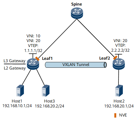
In distributed VXLAN gateway scenarios, leaf nodes function as both Layer 2 and Layer 3 VXLAN gateways. Spine nodes are unaware of the VXLAN tunnels and only forward VXLAN packets between different leaf nodes. On the control plane, a VXLAN tunnel only needs to be set up between leaf nodes. In Figure 1, a VXLAN tunnel is established between Leaf1 and Leaf2 for Host1 and Host2 or Host3 and Host2 to communicate. Because Host1 and Host3 both connect to Leaf1, they can directly communicate through Leaf1 instead of over a VXLAN tunnel.

A VXLAN tunnel is determined by a pair of VTEP IP addresses. When a local VTEP receives the same remote VTEP IP address repeatedly, only one VXLAN tunnel can be established, but packets are encapsulated with different VNIs before being forwarded through the tunnel.
In distributed gateway scenarios, BGP EVPN can be used to dynamically establish VXLAN tunnels in either of the following situations:
Intra-subnet Communication
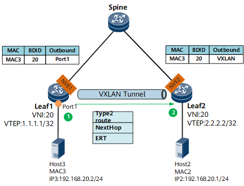
On the network shown in Figure 2, intra-subnet communication between Host2 and Host3 requires only Layer 2 forwarding. The process for establishing a VXLAN tunnel using BGP EVPN is as follows.
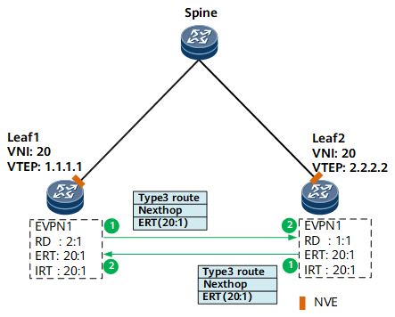
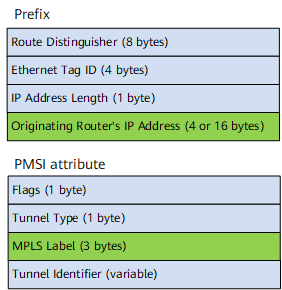
First, a BGP EVPN peer relationship is established between Leaf1 and Leaf2. Then, Layer 2 broadcast domains are created on Leaf1 and Leaf2, and VNIs are bound to the Layer 2 broadcast domains. Next, an EVPN instance is configured in each Layer 2 broadcast domain, and an RD, an ERT, and an IRT are configured for the EVPN instance. After the local VTEP IP address is configured on Leaf1 and Leaf2, they generate a BGP EVPN route and send it to each other. The BGP EVPN route carries the local EVPN instance's ERT and an inclusive multicast route (Type 3 route defined in BGP EVPN). Figure 3 shows the format of an inclusive multicast route, which comprises a prefix and a PMSI attribute. VTEP IP addresses are stored in the Originating Router's IP Address field in the inclusive multicast route prefix, and VNIs are stored in the MPLS Label field in the PMSI attribute. The VTEP IP address is also included in the Next_Hop attribute.
After Leaf1 and Leaf2 receive a BGP EVPN route from each other, they match the ERT of the route against the IRT of the local EVPN instance. If a match is found, the route is accepted. If no match is found, the route is discarded. Leaf1 and Leaf2 obtain the peer VTEP IP address (from the Next_Hop attribute) and VNI carried in the route. If the peer VTEP IP address is reachable at Layer 3, they establish a VXLAN tunnel to the peer end. Moreover, the local end creates a VNI-based ingress replication table and adds the peer VTEP IP address to the table for forwarding BUM packets.
A VPN target is an extended community attribute of BGP. An EVPN instance can have the IRT and ERT configured. The local EVPN instance's ERT must match the remote EVPN instance's IRT for EVPN route advertisement. If not, VXLAN tunnels cannot be dynamically established. If only one end can successfully accept the BGP EVPN route, this end can establish a VXLAN tunnel to the other end, but cannot exchange data packets with the other end. The other end drops packets after confirming that there is no VXLAN tunnel to the end that has sent these packets.
For details about VPN targets, see Basic BGP/MPLS IP VPN Fundamentals.
Inter-Subnet Communication
Inter-subnet communication between Host1 and Host2 requires Layer 3 forwarding. When VXLAN tunnels are established using BGP EVPN, Leaf1 and Leaf2 must advertise host IP routes. Typically, 32-bit host IP routes are advertised. Because different leaf nodes may connect to the same network segment on the VXLAN network, the network segment routes advertised by the leaf nodes may conflict. This conflict may cause host unreachability of some leaf nodes. Leaf nodes can advertise network segment routes in the following scenarios:
The network segment that a leaf node connects to is unique on a VXLAN, and a large number of specific host routes are available. In this case, the routes of the network segment to which the host IP routes belong can be advertised so that leaf nodes do not have to store all these routes.
When hosts on a VXLAN need to access external networks, leaf nodes can advertise routes destined for external networks onto the VXLAN to allow other leaf nodes to learn the routes.
Before establishing a VXLAN tunnel, perform configurations listed in the following table on Leaf1 and Leaf2.
Step |
Function |
|---|---|
Create a Layer 2 broadcast domain and associate a Layer 2 VNI with the Layer 2 broadcast domain. |
A broadcast domain functions as a VXLAN network entity to transmit VXLAN data packets. |
Establish a BGP EVPN peer relationship between Leaf1 and Leaf2. |
This configuration is used to exchange BGP EVPN routes. |
Configure an EVPN instance in a Layer 2 broadcast domain, and configure an RD, an ERT, and an IRT for the EVPN instance. |
This configuration is used to generate BGP EVPN routes. |
Configure L3VPN instances for tenants and bind the L3VPN instances to the VBDIF interfaces of the Layer 2 broadcast domain. |
This configuration is used to differentiate and isolate IP routing tables of different tenants. |
Specify a Layer 3 VNI for an L3VPN instance. |
This configuration allows the leaf nodes to determine the L3VPN routing table for forwarding data packets. |
Configure the export VPN target (eERT) and import VPN target (eIRT) for EVPN routes in the L3VPN instance. |
This configuration controls the local L3VPN instance to advertise and receive BGP EVPN routes. |
Configure the type of route to be advertised between Leaf1 and Leaf2. |
This configuration is used to advertise IP routes between Host1 and Host 2. Two types of routes are available, IRB and IP prefix routes, which can be selected as needed.
|
Dynamic VXLAN tunnel establishment varies depending on how host IP routes are advertised.
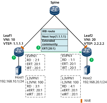
Host IP routes are advertised through IRB routes. (Figure 4 shows the process.)
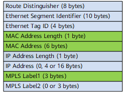
When Host1 communicates with Leaf1 for the first time, Leaf1 learns the ARP entry of Host1 after receiving dynamic ARP packets. Leaf1 then finds the L3VPN instance bound to the VBDIF interface of the Layer 2 broadcast domain where Host1 resides, and obtains the Layer 3 VNI associated with the L3VPN instance. The EVPN instance of Leaf1 then generates an IRB route based on the information obtained. Figure 5 shows the IRB route. The host IP address is stored in the IP Address Length and IP Address fields; the Layer 3 VNI is stored in the MPLS Label2 field.
Leaf1 generates and sends a BGP EVPN route to Leaf2. The BGP EVPN route carries the local EVPN instance's ERT, extended community attribute, Next_Hop attribute, and the IRB route. The extended community attribute carries the tunnel type (VXLAN tunnel) and local VTEP MAC address; the Next_Hop attribute carries the local VTEP IP address.
After Leaf2 receives the BGP EVPN route from Leaf1, Leaf2 processes the route as follows:
If the ERT carried in the route is the same as the IRT of the local EVPN instance, the route is accepted. After the EVPN instance obtains IRB routes, it can extract ARP routes from the IRB routes for the advertisement of host ARP entries.
If the ERT carried in the route is the same as the eIRT of the local L3VPN instance, the route is accepted. Then, the L3VPN instance obtains the IRB route carried in the route, extracts the host IP address and Layer 3 VNI of Host1, and saves the host IP route of Host1 to the routing table. The outbound interface is obtained through recursion based on the next hop of the route. The final recursion result is the VXLAN tunnel to Leaf1, as shown in Figure 6.
A BGP EVPN route is discarded only when the ERT in the route is different from the local EVPN instance's IRT and local L3VPN instance's eIRT.
If the route is accepted by the EVPN instance or L3VPN instance, Leaf2 obtains Leaf1's VTEP IP address from the Next_Hop attribute. If the VTEP IP address is routable at Layer 3, a VXLAN tunnel to Leaf1 is established.
Leaf1 establishes a VXLAN tunnel to Leaf2 through a similar process.
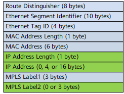
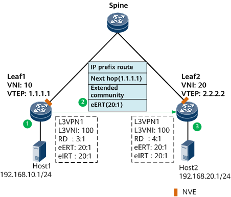
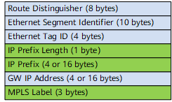
Host IP routes are advertised through IP prefix routes, as shown in Figure 7.
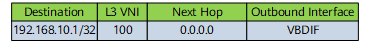
Leaf1 generates a direct route to Host1's IP address. Then, Leaf1 has an L3VPN instance configured to import the direct route, so that Host1's IP route is saved to the routing table of the L3VPN instance and the Layer 3 VNI associated with the L3VPN instance is added. Figure 8 shows the local host IP route.
If network segment route advertisement is required, use a dynamic routing protocol, such as OSPF. Then configure an L3VPN instance to import the routes of the dynamic routing protocol.
Leaf1 is configured to advertise IP prefix routes in the L3VPN instance. Figure 9 shows the IP prefix route. The host IP address is stored in the IP Prefix Length and IP Prefix fields; the Layer 3 VNI is stored in the MPLS Label field. Leaf1 generates and sends a BGP EVPN route to Leaf2. The BGP EVPN route carries the local L3VPN instance's eERT, extended community attribute, Next_Hop attribute, and the IP prefix route. The extended community attribute carries the tunnel type (VXLAN tunnel) and local VTEP MAC address; the Next_Hop attribute carries the local VTEP IP address.
After Leaf2 receives the BGP EVPN route from Leaf1, Leaf2 processes the route as follows:
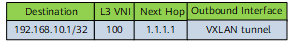
Matches the eERT of the route against the eIRT of the local L3VPN instance. If a match is found, the route is accepted. Then, the L3VPN instance obtains the IP prefix type route carried in the route, extracts the host IP address and Layer 3 VNI of Host1, and saves the host IP route of Host1 to the routing table. The outbound interface is obtained through recursion based on the next hop of the route. The final recursion result is the VXLAN tunnel to Leaf1, as shown in Figure 10.
If the route is accepted by the EVPN instance or L3VPN instance, Leaf2 obtains Leaf1's VTEP IP address from the Next_Hop attribute. If the VTEP IP address is routable at Layer 3, a VXLAN tunnel to Leaf1 is established.
Leaf1 establishes a VXLAN tunnel to Leaf2 through a similar process.
Dynamic MAC address learning
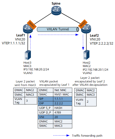
VXLAN supports dynamic MAC address learning to allow communication between tenants. MAC address entries are dynamically created and do not need to be manually maintained, greatly reducing maintenance workload. In distributed VXLAN gateway scenarios, inter-subnet communication requires Layer 3 forwarding; MAC address learning is implemented using dynamic ARP packets between the local host and gateway. The following example illustrates dynamic MAC address learning for intra-subnet communication of hosts on the network shown in Figure 11.
Host3 sends dynamic ARP packets when it first communicates with Leaf1. Leaf1 learns the MAC address of Host3 and the mapping between the BDID and packet inbound interface (that is, the physical interface Port 1 corresponding to the Layer 2 sub-interface), and generates a MAC address entry about Host3 in the local MAC address table, with the outbound interface being Port 1. Leaf1 generates a BGP EVPN route based on the ARP entry of Host3 and sends it to Leaf2. The BGP EVPN route carries the local EVPN instance's ERT, Next_Hop attribute, and a Type 2 route (MAC/IP route) defined in BGP EVPN. The Next_Hop attribute carries the local VTEP's IP address. The MAC Address Length and MAC Address fields identify Host3's MAC address. The Layer 2 VNI is stored in the MPLS Label1 field. Figure 12 shows the format of a MAC route or an IP route.
After receiving the BGP EVPN route from Leaf1, Leaf2 matches the ERT of the EVPN instance carried in the route against the IRT of the local EVPN instance. If a match is found, the route is accepted. If no match is found, the route is discarded. After accepting the route, Leaf2 obtains the MAC address of Host3 and the mapping between the BDID and the VTEP IP address (Next_Hop attribute) of Leaf1, and generates the MAC address entry of the Host3 in the local MAC address table. The outbound interface is obtained through recursion based on the next hop, and the final recursion result is the VXLAN tunnel destined for Leaf1.
Leaf1 learns the MAC route of Host2 through a similar process.
Leaf nodes can learn the MAC addresses of hosts during data forwarding, depending on their capabilities to learn MAC addresses from data packets. If VXLAN tunnels are established using BGP EVPN, leaf nodes can dynamically learn the MAC addresses of hosts through BGP EVPN routes, rather than during data forwarding.
Intra-subnet Forwarding of Known Unicast Packets
Intra-subnet known unicast packets are forwarded only between Layer 2 VXLAN gateways and are unknown to Layer 3 VXLAN gateways. Figure 13 shows the forwarding process of known unicast packets.
- After Leaf1 receives a packet from Host3, it determines the Layer 2 broadcast domain of the packet based on the access interface and VLAN information, and searches for the outbound interface and encapsulation information in the broadcast domain.
- Leaf1's VTEP performs VXLAN encapsulation based on the obtained encapsulation information and forwards the packet through the outbound interface obtained.
- After the VTEP on Leaf2 receives the VXLAN packet, it checks the UDP destination port number, source and destination IP addresses, and VNI of the packet to determine the packet validity. Leaf2 obtains the Layer 2 broadcast domain based on the VNI and performs VXLAN decapsulation to obtain the inner Layer 2 packet.
- Leaf2 obtains the destination MAC address of the inner Layer 2 packet, adds a VLAN tag to the packet based on the outbound interface and encapsulation information in the local MAC address table, and forwards the packet to Host2.
Host2 sends packets to Host3 through a similar process.
Intra-subnet Forwarding of BUM Packets
Intra-subnet BUM packets are forwarded only between Layer 2 VXLAN gateways, and are unknown to Layer 3 VXLAN gateways. Intra-subnet BUM packets can be forwarded in ingress replication mode. In this mode, when a BUM packet enters a VXLAN tunnel, the access-side VTEP performs VXLAN encapsulation, and then forwards the packet to all egress VTEPs that are in the ingress replication list. When the BUM packet leaves the VXLAN tunnel, the egress VTEP decapsulates the packet. Figure 14 shows the forwarding process of BUM packets.
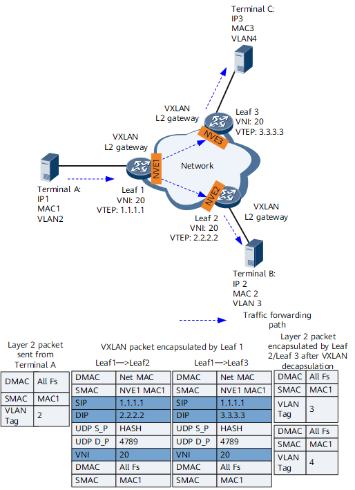
- After Leaf1 receives a packet from TerminalA, it determines the Layer 2 broadcast domain of the packet based on the access interface and VLAN information in the packet.
- Leaf1's VTEP obtains the ingress replication list for the VNI, replicates the packet based on the list, and performs VXLAN encapsulation. Leaf1 then forwards the VXLAN packet through the outbound interface.
- After the VTEP on Leaf2 or Leaf3 receives the VXLAN packet, it checks the UDP destination port number, source and destination IP addresses, and VNI of the packet to determine the packet validity. Leaf2 or Leaf3 obtains the Layer 2 broadcast domain based on the VNI and performs VXLAN decapsulation to obtain the inner Layer 2 packet.
- Leaf2 or Leaf3 checks the destination MAC address of the inner Layer 2 packet and finds it a BUM MAC address. Therefore, Leaf2 or Leaf3 broadcasts the packet onto the network connected to terminals (not the VXLAN tunnel side) in the Layer 2 broadcast domain. Specifically, Leaf2 or Leaf3 finds the outbound interfaces and encapsulation information not related to the VXLAN tunnel, adds VLAN tags to the packet, and forwards the packet to TerminalB or TerminalC.
The forwarding process of a response packet from TerminalB/TerminalC to TerminalA is similar to the intra-subnet forwarding process of known unicast packets.
Inter-subnet Packet Forwarding
Inter-subnet packets must be forwarded through a Layer 3 gateway. Figure 15 shows the inter-subnet packet forwarding process in distributed VXLAN gateway scenarios.
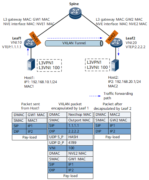
- After Leaf1 receives a packet from Host1, it finds that the destination MAC address of the packet is a gateway MAC address so that the packet must be forwarded at Layer 3.
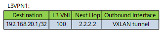
- Leaf1 first determines the Layer 2 broadcast domain of the packet based on the inbound interface and then finds the L3VPN instance to which the VBDIF interface of the Layer 2 broadcast domain is bound. Leaf1 searches the routing table of the L3VPN instance for a matching host route based on the destination IP address of the packet and obtains the Layer 3 VNI and next hop address corresponding to the route. Figure 16 shows the host route in the L3VPN routing table. If the outbound interface is a VXLAN tunnel, Leaf1 determines that VXLAN encapsulation is required and then:
- Obtains MAC addresses based on the VXLAN tunnel's source and destination IP addresses and replaces the source and destination MAC addresses in the inner Ethernet header.
- Encapsulates the Layer 3 VNI into the packet.
- Encapsulates the VXLAN tunnel's destination and source IP addresses in the outer header. The source MAC address is the MAC address of the outbound interface on Leaf1, and the destination MAC address is the MAC address of the next hop.
- The VXLAN packet is then transmitted over the IP network based on the IP and MAC addresses in the outer headers and finally reaches Leaf2.
- After Leaf2 receives the VXLAN packet, it decapsulates the packet and finds that the destination MAC address is its own MAC address. It then determines that the packet must be forwarded at Layer 3.
- Leaf2 finds the corresponding L3VPN instance based on the Layer 3 VNI carried in the packet. Then, Leaf2 searches the routing table of the L3VPN instance and finds that the next hop of the packet is the gateway interface address. Leaf2 then replaces the destination MAC address with the MAC address of Host2, replaces the source MAC address with the MAC address of Leaf2, and forwards the packet to Host2.
Host2 sends packets to Host1 in a similar process.
When Huawei devices need to communicate with non-Huawei devices, ensure that the non-Huawei devices use the same forwarding mode. Otherwise, the Huawei devices may fail to communicate with non-Huawei devices.