Basic Functions
Function Overview
Fault management functions include continuity check (CC), loopback (LB), and linktrace (LT). The principles of Y.1731 fault management are the same as those of CFM fault management.
Performance monitoring functions include single- and dual-ended frame loss measurement, one- and two-way frame delay measurement, alarm indication signal (AIS), Ethernet test function (ETH-Test), Single-ended Synthetic Loss Measurement (SLM), Ethernet lock signal function (ETH-LCK), ETH-BN on virtual private LAN service (VPLS) networks, virtual leased line (VLL) networks, and virtual local area networks (VLANs). BGP VPLS and VLL scenarios support AIS only.
Function |
Description |
Usage Scenario |
|---|---|---|
Collects frame loss statistics to assess the quality of links between MEPs, independent of continuity check (CC). |
To collect frame loss statistics, select either single- or dual-ended frame loss measurement:
|
|
Collects frame loss statistics to assess link quality on CFM CC-enabled devices. |
To collect frame loss statistics, select either single- or dual-ended frame loss measurement:
|
|
Measures the network delay on a unidirectional link between MEPs. |
To measure the link delay, select either one- or two-way frame delay measurement:
|
|
Measures the network delay on a bidirectional link between MEPs. |
||
Detects server-layer faults and suppresses alarms, minimizing the impact on network management systems (NMSs). |
AIS is used to suppresses local alarms when faults must be rapidly detected. |
|
Verifies bandwidth throughput and bit errors. |
|
|
Informs the server-layer (sub-layer) MEP of administrative locking and the interruption of traffic destined for the MEP in the inner maintenance domain (MD). |
The ETH-LCK function must work with the ETH-Test function. |
|
Collects frame loss statistics on point-to-multipoint or E-Trunk links to monitor link quality. |
Single-ended synthetic frame LM is used to collect accurate frame loss statistics on point-to-multipoint links. |
|
Enables server-layer MEPs to notify client-layer MEPs of the server layer's connection bandwidth when routing devices connect to microwave devices. The server-layer devices are microwave devices, and the client-layer devices are routing devices. Routing devices can only function as ETH-BN packets' receive ends and must work with microwave devices to implement this function. |
When routing devices connect to microwave devices, enable the ETH-BN receiving function on the routing devices to associate bandwidth with the microwave devices. |
ETH-LM
Ethernet frame loss measurement (ETH-LM) enables a local MEP and its RMEP to exchange ETH-LM frames to collect frame loss statistics on E2E links. ETH-LM modes are classified as near- or far-end ETH-LM.
Near-end ETH-LM applies to an inbound interface, and far-end ETH-LM applies to an outbound interface on a MEP. ETH-LM counts the number of errored frame seconds to determine the duration during which a link is unavailable.
Single-ended frame loss measurement
This method measures frame loss proactively or on demand.On-demand measurement collects single-ended frame loss statistics at a time or a specific number of times for diagnosis.
Proactive measurement collects single-ended frame loss statistics periodically.
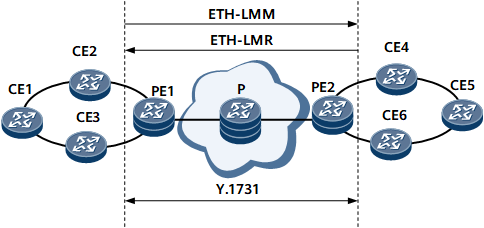
A local MEP sends a loss measurement message (LMM) carrying an ETH-LM request to its RMEP. After receiving the request, the RMEP responds with a loss measurement reply (LMR) carrying an ETH-LM response. Figure 1 illustrates the process for single-ended frame loss measurement.
After single-ended frame loss measurement is enabled, a MEP on PE1 sends an RMEP on PE2 an ETH-LMM carrying an ETH-LM request. The MEP then receives an ETH-LMR message carrying an ETH-LM response from the RMEP on PE2. The ETH-LMM carries a local transmit counter TxFCl (with a value of TxFCf), indicating the time when the message was sent by the local MEP. After receiving the ETH-LMM, PE2 replies with an ETH-LMR message, which carries the following information:
TxFCf: copied from the ETH-LMM
RxFCf: value of the local counter RxFCl at the time of ETH-LMM reception
TxFCb: value of the local counter TxFCl at the time of ETH-LMM transmission
After receiving the ETH-LMR message, PE1 measures near- and far-end frame loss based on the following values:
Received ETH-LMR message's TxFCf, RxFCf, and TxFCb values and local counter RxFCl value that is the time when this ETH-LMR message was received. These values are represented as TxFCf[tc], RxFCf[tc], TxFCb[tc], and RxFCl[tc].
tc is the time when this ETH-LMR message was received.
Previously received ETH-LMR message's TxFCf, RxFCf, and TxFCb values and local counter RxFCl value that is the time when this ETH-LMR message was received. These values are represented as TxFCf[tp], RxFCf[tp], TxFCb[tp], and RxFCl[tp].
tp is the time when the previous ETH-LMR message was received.
Far-end frame loss = |TxFCf[tc] - TxFCf[tp]| - |RxFCf[tc] - RxFCf[tp]|
Near-end frame loss = |TxFCb[tc] - TxFCb[tp]| - |RxFCl[tc] - RxFCl[tp]|
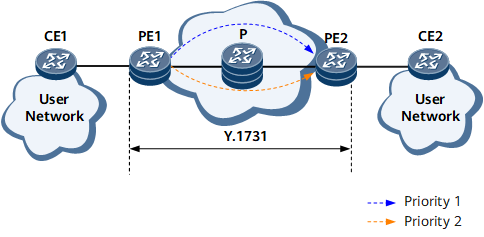
Service packets are prioritized based on 802.1p priorities and are transmitted using different policies. Traffic passing through the P device on the network shown in Figure 2 carries 802.1p priorities of 1 and 2.
Single-ended frame loss measurement is enabled on PE1 to send traffic with a priority of 1 to measure frame loss on a link between PE1 and PE2. Traffic with a priority of 2 is also sent. After receiving traffic with priorities of 1 and 2, the P device forwards traffic with a higher priority, delaying the arrival of traffic with a priority of 1 at PE2. As a result, the frame loss ratio is inaccurate.
802.1p priority-based single-ended frame loss measurement can be enabled to obtain accurate results.
Dual-ended frame loss measurement
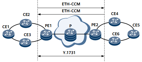
This method measures frame loss periodically, implementing error management. Each MEP sends its RMEP a dual-ended ETH-LM message. After receiving an ETH-LM message, a MEP collects near- and far-end frame loss statistics but does not forward the ETH-LM message. Figure 3 illustrates the process for dual-ended frame loss measurement.
After dual-ended frame loss measurement is configured, each MEP periodically sends a CCM carrying a request to its RMEP. After receiving the CCM, the RMEP collects near- and far-end frame loss statistics but does not forward the message. The CCM carries the following information:
TxFCf: value of the local counter TxFCl at the time of CCM transmission
RxFCb: value of the local counter RxFCl at the time of the reception of the last CCM
TxFCb: value of TxFCf in the last received CCM
PE1 uses received information to measure near- and far-end frame loss based on the following values:
Received CCM's TxFCf, RxFCb, and TxFCb values and local counter RxFCl value that is the time when this CCM was received. These values are represented as TxFCf[tc], RxFCb[tc], TxFCb[tc], and RxFCl[tc].
tc is the time when this CCM was received.
Previously received CCM's TxFCf, RxFCb, and TxFCb values and local counter RxFCl value that is the time when this CCM was received. These values are represented as TxFCf[tp], RxFCb[tp], TxFCb[tp], and RxFCl[tp].
tp is the time when the previous CCM was received.
Far-end frame loss = |TxFCb[tc] - TxFCb[tp]| - |RxFCb[tc] - RxFCb[tp]|
Near-end frame loss = |TxFCf[tc] - TxFCb[tp]| - |RxFCl[tc] - RxFCl[tp]|
ETH-DM
Delay measurement (DM) measures the delay and its variation. A MEP sends its RMEP a message carrying ETH-DM information and receives a response message carrying ETH-DM information from its RMEP.
One-way frame delay measurement
A MEP sends its RMEP a 1DM message carrying one-way ETH-DM information. After receiving this message, the RMEP measures the one-way frame delay and its variation.
One-way frame delay measurement can be implemented only after the MEP synchronizes the time with its RMEP. The delay variation can be measured regardless of whether the MEP synchronizes the time with its RMEP. If a MEP synchronizes its time with its RMEP, the one-way frame delay and its variation can be measured. If the time is not synchronized, only the one-way delay variation can be measured.
One-way frame delay measurement can be implemented in either of the following modes:On-demand measurement: calculates the one-way frame delay at a time or a specific number of times for diagnosis.
Proactive measurement: calculates the one-way frame delay periodically.
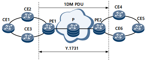
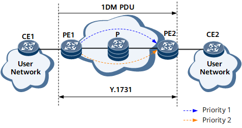
Figure 4 illustrates the process for one-way frame delay measurement.
One-way frame delay measurement is implemented on an E2E link between a local MEP and its RMEP. The local MEP sends 1DMs to the RMEP and then receives replies from the RMEP. After one-way frame delay measurement is configured, a MEP periodically sends 1DMs carrying TxTimeStampf (the time when the 1DM was sent). After receiving the 1DM, the RMEP parses TxTimeStampf and compares this value with RxTimef (the time when the DM frame was received). The RMEP calculates the one-way frame delay based on these values using the following equation:
Frame delay = RxTimef - TxTimeStampf
The frame delay can be used to measure the delay variation.
A delay variation is an absolute difference between two delays.
802.1p priorities carried in service packets are used to prioritize services. Traffic passing through the P device on the network shown in Figure 5 carries 802.1p priorities of 1 and 2.
One-way frame delay measurement is enabled on PE1 to send traffic with a priority of 1 to measure the frame delay on a link between PE1 and PE2. Traffic with a priority of 2 is also sent. After receiving traffic with priorities of 1 and 2, the P device forwards traffic with a higher priority, delaying the arrival of traffic with a priority of 1 at PE2. As a result, the frame delay calculated on PE2 is inaccurate.
802.1p priority-based one-way frame delay measurement can be enabled to obtain accurate results.
Two-way frame delay measurement
A MEP sends its RMEP a delay measurement message (DMM) carrying an ETH-DM request. After receiving the DMM, the RMEP sends the MEP a delay measurement reply (DMR) carrying an ETH-DM response.
Two-way frame delay measurement can be implemented in either of the following modes:On-demand measurement: calculates the two-way frame delay at a time for diagnosis.
Proactive measurement: calculates the two-way frame delay periodically.
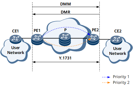
Figure 6 illustrates the process for two-way frame delay measurement.
Two-way frame delay measurement is performed by a local MEP to send a delay measurement message (DMM) to its RMEP and then receive a DMR from the RMEP. After two-way frame delay measurement is configured, a MEP periodically sends DMMs carrying TxTimeStampf (the time when the DMM was sent). After receiving the DMM, the RMEP replies with a DMR message. This message carries RxTimeStampf (the time when the DMM was received) and TxTimeStampb (the time when the DMR was sent). The value in every field of the DMM is copied to the DMR, with the exception that the source and destination MAC addresses were interchanged. Upon receipt of the DMR message, the MEP calculates the two-way frame delay using the following equation:
Frame delay = (RxTimeb - TxTimeStampf) - (TxTimeStampb - RxTimeStampf)
The frame delay can be used to measure the delay variation.
A delay variation is an absolute difference between two delays.
802.1p priorities carried in service packets are used to prioritize services. Traffic passing through the P device on the network shown in Figure 7 carries 802.1p priorities of 1 and 2.
Two-way frame delay measurement is enabled on PE1 to send traffic with a priority of 1 to measure the frame delay on a link between PE1 and PE2. Traffic with a priority of 2 is also sent. After receiving traffic with priorities of 1 and 2, the P device forwards traffic with a higher priority, delaying the arrival of traffic with a priority of 1 at PE2. As a result, the frame delay calculated on PE2 is inaccurate.
802.1p priority-based two-way frame delay measurement can be enabled to obtain accurate results.
AIS
AIS is a protocol used to transmit fault information.
If CFM detects a fault in the link between AIS-enabled PEs, CFM sends AIS packet data units (PDUs) to CEs. After receiving the AIS PDUs, the CEs suppress alarms, minimizing the impact of a large number of alarms on a network management system (NMS).
After the link between the PEs recovers, the PEs stop sending AIS PDUs. CEs do not receive AIS PDUs during a period of 3.5 times the interval at which AIS PDUs are sent. Therefore, the CEs cancel the alarm suppression function.
ETH-Test
ETH-Test is used to perform one-way on-demand in-service or out-of-service diagnostic tests on the throughput, frame loss, and bit errors.
Verifying throughput and frame loss: Throughput means the maximum bandwidth of a link without packet loss. When you use ETH-Test to verify the throughput, a MEP sends frames with ETH-Test information at a preconfigured traffic rate and collects frame loss statistics for a specified period. If the statistical results show that the number of sent frames is greater than the number of received frames, frame loss occurs. The MEP sends frames at a lower rate until no frame loss occurs. The traffic rate measured at the time when no packet loss occurs is the throughput of this link.
Verifying bit errors: ETH-Test is implemented by verifying the cyclic redundancy code (CRC) of the Test TLV field carried in ETH-Test frames. For the ETH-Test implementation, four types of test patterns can be specified in the test TLV field: Null signal without CRC-32, Null signal with CRC-32, PRBS 2-31-1 without CRC-32, and PRBS 2-31-1 with CRC-32. Null signal indicates all 0s signal. PRBS, pseudo random binary sequence, is used to simulate white noise. A MEP sends ETH-Test frames carrying the calculated CRC value to the RMEP. After receiving the ETH-Test frames, the RMEP recalculates the CRC value. If the recalculated CRC value is different from the CRC value carried in the sent ETH-Test frames, bit errors occur.
Out-of-service ETH-Test mode: Client data traffic is interrupted in the diagnosed entity. To resolve this issue, the out-of-service ETH-Test function must be used together with the ETH-LCK function.
In-service ETH-Test mode: Client data traffic is not interrupted, and the frames with the ETH-Test information are transmitted using part of bandwidths.
ETH-LCK
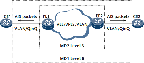
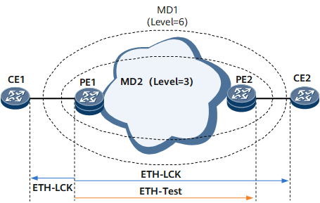
ETH-LCK is used for administrative locking on the MEP in the outer MD with a higher level than the inner MD, that is, preventing CC alarms from being generated in the outer MD. When implementing ETH-LCK, a MEP in the inner MD sends frames with the ETH-LCK information to the MEP in the outer MD. After receiving the frames with the ETH-LCK information, the MEP in the outer MD can differentiate the alarm suppression caused by administrative locking from the alarm suppression caused by a fault in the inner MD (the AIS function).
To suppress CC alarms from being generated in the outer MD, ETH-LCK is implemented with out-of-service ETH-Test. A MEP in the inner MD with a lower level initiates ETH-Test by sending an ETH-LCK frame to a MEP in the outer MD. Upon receipt of the ETH-LCK frame, the MEP in the outer MDsuppresses all CC alarms immediately and reports an ETH-LCK alarm indicating administrative locking. Before out-of-service ETH-Test is complete, the MEP in the inner MD sends ETH-LCK frames to the MEP in the outer MD. After out-of-service ETH-Test is complete, the MEP in the inner MD stops sending ETH-LCK frames. If the MEP in the outer MD does not receive ETH-LCK frames for a period 3.5 times provided that; if the specified interval, it releases the alarm suppression and reports a clear ETH-LCK alarm.
As shown in Figure 9, MD2 with the level of 3 is configured on PE1 and PE2; MD1 with the level of 6 is configured on CE1 and CE2. When PE1's MEP1 sends out-of-service ETH-Test frames to PE2's MEP2, MEP1 also sends ETH-LCK frames to CE1's MEP11 and CE2's MEP22 separately to suppress MEP11 and MEP22 from generating CC alarms. When MEP1 stops sending out-of-service ETH-Test frames, it also stops sending ETH-LCK frames. If MEP11 and MEP22 do not receive ETH-LCK frames for a period 3.5 times provided that; if the specified interval, they release the alarm suppression.
Single-ended ETH-SLM
SLM measures frame loss using synthetic frames instead of data traffic. When implementing SLM, the local MEP exchanges frames containing ETH-SLM information with one or more RMEPs.
- The local MEP sends ETH-SLM request frames to the RMEPs.
- After receiving the ETH-SLM request frames, the RMEPs send ETH-SLM reply frames to the local MEP.
A frame with the single-ended ETH-SLM request information is called an SLM, and a frame with the single-ended ETH-SLM reply information is called an SLR. SLM frames carry SLM protocol data units (PDUs), and SLR frames carry SLR PDUs.
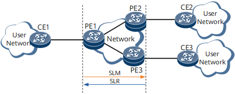
Single-ended SLM and single-ended frame LM are differentiated as follows: On the point-to-multipoint network shown in Figure 10, inward MEPs are configured on PE1's and PE3's interfaces, and single-ended frame LM is performed on the PE1-PE3 link. Traffic coming through PE1's interface is destined for both PE2 and PE3, and single-ended frame LM will collect frame loss statistics for all traffic, including the PE1-to-PE2 traffic. As a result, the collected statistics are not accurate. Unlike singled-ended frame LM, single-ended SLM collects frame loss statistics only for the PE1-to-PE3 traffic, which is more accurate.
When implementing single-ended SLM, PE1 sends SLM frames to PE3 and receives SLR frames from PE3. SLM frames contain TxFCf, the value of TxFCl (frame transmission counter), indicating the frame count at the transmit time. SLR frames contain the following information:
TxFCf: value of TxFCl (frame transmission counter) indicating the frame count on PE1 upon the SLM transmission
TxFCb: value of RxFC1 (frame receive counter) indicating the frame count on PE3 upon the SLR transmission
After receiving the last SLR frame during a measurement period, a MEP on PE1 measures the near-end and far-end frame loss based on the following values:
Last received SLR's TxFCf and TxFCb, and value of RxFC1 (frame receive counter) indicating the frame count on PE1 upon the SLR reception. These values are represented as TxFCf[tc], TxFCb[tc], and RxFCl[tc].
tc indicates the time when the last SLR frame was received during the measurement period.
Previously received SLR's TxFCf and TxFCb, and value of RxFC1 (frame receive counter) indicating the frame count on PE1 upon the SLR reception. These values are represented as TxFCf[tp], TxFCb[tp], and RxFCl[tp].
tp indicates the time when the last SLR frame was received during the previous measurement period.
Far-end frame loss = |TxFCf[tc] – TxFCf[tp]| – |TxFCb[tc] – TxFCb[tp]|
Near-end frame loss = |TxFCb[tc] – TxFCb[tp]| – |RxFCf[tc] – RxFCf[tp]|
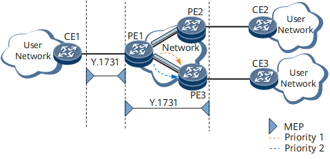
On a network, each packet carries the IEEE 802.1p field, indicating its priority. According to packet priority, different QoS policies will be applied. On the network shown in Figure 11, the PE1-to-PE3 traffic has two priorities: 1 and 2, as indicated by the IEEE 802.1p field.
When implementing single-ended SLM for traffic over the PE1-PE3 link, PE1 sends SLM frames with varied priorities and checks the frame loss. Based on the check result, the network administrator can adjust the QoS policy for the link.
ETH-BN
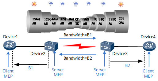
Ethernet bandwidth notification (ETH-BN) enables server-layer MEPs to notify client-layer MEPs of the server layer's connection bandwidth when routing devices connect to microwave devices. The server-layer devices are microwave devices, which dynamically adjust the bandwidth according to the prevailing atmospheric conditions. The client-layer devices are routing devices. Routing devices can only function as ETH-BN packets' receive ends and must work with microwave devices to implement this function.
If the ETH-BN function has been enabled on the server-layer devices Device2 and Device3 and the bandwidth of the server-layer devices' microwave links decreases, the server-layer devices send ETH-BN packets to the client-layer devices (Device1 and Device4). After receiving the ETH-BN packets, the client-layer MEPs can use bandwidth information in the packets to adjust service policies, for example, to reduce the rate of traffic sent to the degraded links.
When the server-layer devices' microwave links work properly, whether to send ETH-BN packets is determined by the configuration of the server-layer devices. When the server-layer microwave devices stop sending ETH-BN packets, the client-layer devices do not receive any ETH-BN packets. The ETH-BN data on the client-layer devices is aged after 3.5 times the interval at which ETH-BN packets are sent.

When planning ETH-BN, you must check that the service burst traffic is consistent with a device's buffer capability.
Usage Scenario
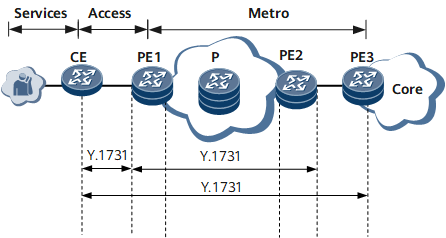
Y.1731 supports performance statistics collection on both end-to-end and end-to-multi-end links.
End-to-end performance statistics collection
On the network shown in Figure 13, Y.1731 collects statistics about the end-to-end link performance between the CE and PE1, between PE1 and PE2, or between the CE and PE3.
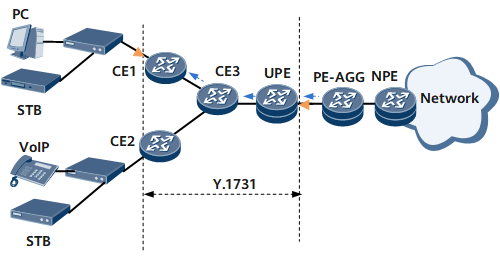
End-to-multi-end performance statistics collection
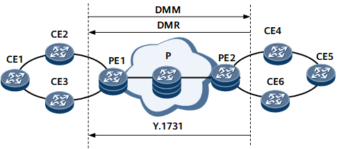
On the network shown in Figure 14, user-to-network traffic from different users traverses CE1 and CE2 and is converged on CE3. CE3 forwards the converged traffic to the UPE. Network-to-user traffic traverses CE3, and CE3 forwards the traffic to CE1 and CE2.
When Y.1731 is used to collect statistics about the link performance between the CE and the UPE, end-to-end performance statistics collection cannot be implemented. This is because only one inbound interface (on the UPE) sends packets but two outbound interfaces (on CE1 and CE2) receive the packets. In this case, statistics on the outbound interfaces fail to be collected. To resolve this issue, end-to-multi-end performance statistics collection can be implemented.
The packets carry the MAC address of CE1 or CE2. The UPE identifies the outbound interface based on the destination MAC address carried in the packets and collects end-to-end performance statistics.
Both end-to-multi-end and end-to-end performance statistics collection applies to VLL, VPLS, and VLAN scenarios and has the same statistics collection principles.