Basic LLDP Concepts
LLDP Frames
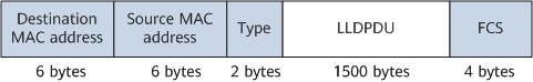
LLDP frames are Ethernet frames encapsulated with LLDP data units (LLDPDUs). LLDP frames support two encapsulation modes: Ethernet II and Subnetwork Access Protocol (SNAP). Currently, the NetEngine 8000 F supports the Ethernet II encapsulation mode.
Figure 1 shows the format of an Ethernet II LLDP frame.
Field |
Description |
|---|---|
Destination MAC address |
A fixed multicast MAC address 0x0180-C200-000E. |
Source MAC address |
A MAC address for an interface or a bridge MAC address for a device (Use the MAC address for an interface if there is one; otherwise, use the bridge MAC address for a device). |
Type |
Packet type, fixed at 0x88CC. |
LLDPDU |
Main body of an LLDP frame. |
FCS |
Frame check sequence. |
LLDPDU
An LLDPDU is a data unit encapsulated in the data field in an LLDP frame.
A device encapsulates local device information in type-length-value (TLV) format and combines several TLVs into an LLDPDU for transmission. You can combine various TLVs to form an LLDPDU as required. TLVs allow a device to advertise its own status and learn the status of neighboring devices.
Figure 2 shows the LLDPDU format.
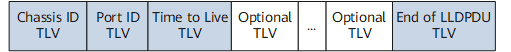
Each LLDPDU carries a maximum of 28 types of TLVs, and that each LLDPDU starts with the Chassis ID TLV, Port ID TLV, and Time to Live TLV, and ends with the End of LLDPDU TLV. These four TLVs are mandatory. Additional TLVs are selected as needed.
TLV
A TLV is the smallest unit of an LLDPDU. It gives type, length, and other information for a device object. For example, a device ID is carried in the Chassis ID TLV, an interface ID in the Port ID TLV, and a network management address in the Management Address TLV.
LLDPDUs can carry basic TLVs, TLVs defined by IEEE 802.1, TLVs defined by IEEE 802.3, and Data Center Bridging Capabilities Exchange Protocol (DCBX) TLVs.
Basic TLVs: are the basis for network device management.
Table 2 Basic TLVs TLV Name
TLV Type Value
Description
Mandatory
End of LLDPDU TLV
0
End of an LLDPDU.
Yes
Chassis ID TLV
1
Bridge MAC address of the transmit device.
Yes
Port ID TLV
2
Number of a transmit interface of a device.
Yes
Time To Live TLV
3
Time to live of the local device information stored on a neighbor device.
Yes
Port Description TLV
4
String describing an Ethernet interface.
No
System Name TLV
5
Device name.
No
System Description TLV
6
System description.
No
System Capabilities TLV
7
Primary functions of the system and whether these primary functions are enabled.
No
Management Address TLV
8
Management address.
No
Reserved
9–126
Reserved for special use.
No
Organizationally Specific TLVs
127
TLVs defined by organizations.
No
Organizationally specific TLVs: include TLVs defined by IEEE 802.1 and those defined by IEEE 802.3. They are used to enhance network device management. Use these TLVs as needed.
TLVs defined by IEEE 802.1
Table 3 Description of TLVs defined by IEEE 802.1 TLV Name
TLV Type Value
Description
Reserved
0
Reserved for special use.
Port VLAN ID TLV
1
VLAN ID on an interface.
Port And Protocol VLAN ID TLV
2
Protocol VLAN ID on an interface.
VLAN Name TLV
3
VLAN name on an interface.
Protocol Identity TLV
4
A set of protocols supported by an interface.
Reserved
5–255
Reserved for special use.
TLVs defined by IEEE 802.3
Table 4 Description of TLVs defined by IEEE 802.3 TLV Name
TLV Type
Description
Reserved
0
Reserved for special use.
MAC/PHY Configuration/Status TLV
1
Whether the interface supports rate auto-negotiation, whether auto-negotiation is enabled, as well as the current bit-rate and duplex settings of the device.
Power Via MDI TLV
2
Power supply capability of an interface, that is, whether an interface supplies or requires power.
Link Aggregation TLV
3
Link aggregation status.
Maximum Frame Size TLV
4
Maximum frame length supported by interfaces. The maximum transmission unit (MTU) of an interface is used.
Reserved
5-255
Reserved for special use.
Figure 3 shows the TLV format.
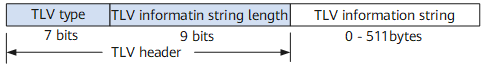
The TLV contains the following fields:
- TLV type: a 7–bit long field. Each value uniquely identifies a TLV type. For example, value 0 indicates the end of LLDPDU TLV, and value 1 indicates a Chassis ID TLV.
- TLV information string length: a 9–bit long field indicating the length of a TLV string.
- TLV information string: a string that contains TLV information. This field contains a maximum of 511 bytes.
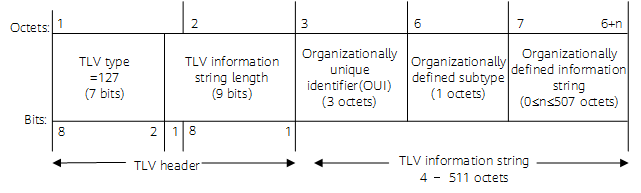
When TLV Type is 127, it indicates that the TLV is an organization-defined TLV. In this case, the TLV structure is shown in Figure 4.
Organizationally unique identifier (OUI) identifies the organization that defines the TLV.
LLDP Management Addresses
LLDP management addresses are used by the NMS to identify devices and implement device management. Management IP addresses uniquely identify network devices, facilitating network topology layout and network management.
- If you do not specify a management address, a device searches the IP address list and automatically selects an IP address as the default management address.
- If the device does not find any proper IP address from the IP address list, the system uses a bridge MAC address as the default management address.

The system searches for the management IP address in the following sequence: IP address of the loopback interface, IP address of the management network interface, and IP address of the VLANIF interface. Among the IP addresses of the same type, the system selects the smallest one as the management address.pac