EVC Service Bearing
Table 1 lists EVC types defined by the MEF.
EVC Type |
Description |
|---|---|
Point to point EVC |
Supports the Ethernet Line (E-Line) service. The E-Line service is an Ethernet service that is based on a point to point EVC. Services are not distinguished in the point to point EVC. |
Multipoint to multipoint EVC |
Supports the Ethernet LAN (E-LAN) service. The E-LAN service is an Ethernet service that is based on a multipoint to multipoint EVC. |
Rooted multipoint EVC |
Point to multi-point |

This section focuses on the multipoint to multipoint EVC.
Related Concepts
EVC Layer 2 sub-interface
An EVC Layer 2 sub-interface is connected to a BD and a VPWS network but cannot be directly connected to a Layer 3 network.
BD
A BD is a broadcast domain. VLAN tags are transparent within a BD, and MAC address learning is based on BDs.
An EVC Layer 2 sub-interface belongs to only one BD. Each EVC Layer 2 sub-interface functioning as a service access point is added to a specific bridge domain and transmits a specific type of service, which implements service isolation.
BDIF
A BDIF interface is a Layer 3 logical interface that terminates Layer 2 services and provides Layer 3 access.
Each BD has only one BDIF interface.
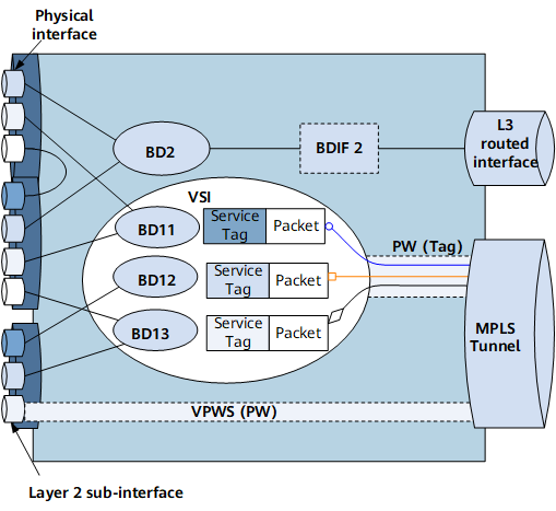
Figure 1 shows a diagram of EVC service bearing, involving EFPs, broadcast domains, and Layer 3 access.
Ethernet Flow Point (EFP)
An EVC Layer 2 sub-interface is used as an EVC service access point, on which traffic encapsulation types and behaviors can be flexibly combined. A traffic encapsulation type and behavior are grouped into a traffic policy. Traffic policies help implement flexible Ethernet traffic access.
Traffic encapsulation
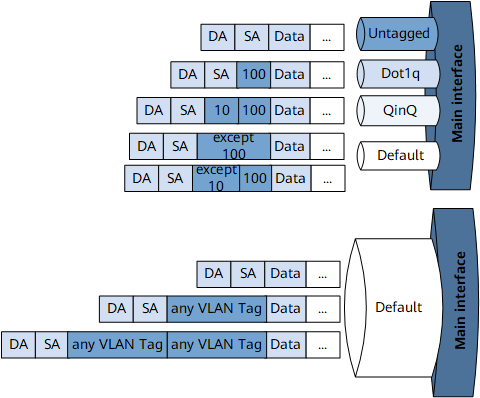
A Layer 2 Ethernet network can transmit untagged, single-tagged, and double-tagged packets. To enable a specific EVC Layer 2 sub-interface to transmit a specific type of packet, specify an encapsulation type on the EVC Layer 2 sub-interface. Table 2 lists traffic encapsulation types supported by Layer 2 sub-interfaces.
Table 2 Traffic encapsulation Type
Description
Rule
Untagged
An EVC Layer 2 sub-interface with this traffic encapsulation type can only receive packets carrying no VLAN tags.
Only one traffic encapsulation type can be configured for each EVC Layer 2 sub-interface.
Dot1q
An EVC Layer 2 sub-interface with this traffic encapsulation type can receive packets carrying one or more tags.
The sub-interface checks the outer VLAN tags in packets, but not the inner tags. It accepts packets in which the outer VLAN tag matches the specified VLAN tag and the inner VLAN tag is either unspecified or does not match a specified QinQ encapsulation type, and transparently transmits inner VLAN tags as data.
QinQ
An EVC Layer 2 sub-interface with this traffic encapsulation type can receive packets carrying two or more tags.
The sub-interface checks the first two tags in packets before accepting them.
Default
An EVC Layer 2 sub-interface with this traffic encapsulation type can receive packets any number of tags. The packets can be untagged, single-tagged, double-tagged, and multi-tagged packets.
For example, where one EVC Layer 2 sub-interface supports untagged encapsulation, and another one supports default encapsulation, the former can receive untagged packets, and the latter can receive all types of packets, except untagged packets.
Figure 2 shows a traffic encapsulation diagram.
On a physical interface, if only one EVC Layer 2 sub-interface is created and the encapsulation type is Default, all traffic is forwarded through the EVC Layer 2 sub-interface.
If a physical interface has both a Default EVC sub-interface and EVC sub-interfaces of other traffic encapsulation types (such as Dot1q and QinQ), and all the non-Default EVC sub-interfaces are Down, traffic precisely matching these non-Default EVC sub-interfaces will not be forwarded through the Default EVC sub-interface.
Different types of sub-interfaces, including common sub-interfaces, Layer 2 sub-interfaces, sub-interfaces for dot1q VLAN tag termination, and sub-interfaces for QinQ VLAN tag termination, can be created on the same interface. Among these sub-interfaces, only Layer 2 sub-interfaces can be connected to BDs and configured with traffic encapsulation, traffic behaviors, traffic policies, and traffic forwarding.
If a default sub-interface is connected to a BD, no BDIF interface can be created in the BD.
Traffic behaviors
Table 3 lists traffic behaviors supported by Layer 2 sub-interfaces.
The rules of the traffic behaviors in Table 3:
- Only one traffic behavior can be configured on each EVC Layer 2 sub-interface.
The traffic behavior for incoming traffic must be the inverse of that for the traffic behavior for outgoing traffic.
- If no traffic behavior is configured on an EVC Layer 2 sub-interface, the sub-interface forwards received packets without modifying them.
Table 3 Traffic behaviors Type
Description
Usage Scenario
Figure
push
An EVC Layer 2 sub-interface with this traffic behavior type adds outer VLAN tags to received packets.- push 1: adds one outer VLAN tag to a packet.
- push 2: adds two VLAN tags to a packet.
On a metro Ethernet network, user and service packets are identified using VLANs. A 12-bit VLAN tag defined in IEEE 802.1Q identifies a maximum of only 4096 VLANs, which is insufficient for a great number of users in the metro Ethernet. The QinQ technology increases the number of available VLAN tags.
After an EVC Layer 2 sub-interface has been created on the access side of a device, adds one or two VLAN tags to untagged and dot1q packets, and adds one VLAN tag to QinQ packets.
Figure 3 push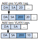
pop
An EVC Layer 2 sub-interface with this traffic behavior type removes VLAN tags from received packets.- pop single: removes a tag from each single-tagged packet or the outer tag from each double-tagged packet.
- pop double: removes both VLAN tags from a packet.
Inter-VLAN communication
VLANs are widely used because they can isolate Layer 2 user packets. Each VLAN logically isolates a broadcast domain from other broadcast domains in a physical LAN. Hosts in each VLAN can communicate with each other, but not hosts in other VLANs. To enable inter-VLAN communication, Layer 3 routing techniques must be used.
Traditional Layer 3 Ethernet interfaces consider VLAN-tagged packets invalid and discard them and do not transmit them over routes. To enable inter-VLAN communication, a pop traffic behavior can be specified on an EVC Layer 2 sub-interface created on the access side of a device on the edge of a public network. Then the EVC Layer 2 sub-interface can remove VLAN tags after receiving VLAN-tagged packets and forward the packets to another VLAN to implement inter-VLAN communication.
LAN and WAN interconnection
A majority of LAN packets carry VLAN tags, whereas WAN protocols, for example, PPP, cannot identify VLAN-tagged packets. To forward VLAN-tagged packets from a LAN to a WAN, a device needs to record the VLAN information, remove VLAN tags from packets, and forward them.
Figure 4 pop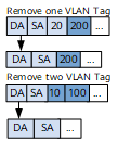
swap
An EVC Layer 2 sub-interface with this traffic behavior type swaps the inner VLAN tag with the outer VLAN tag in a double-tagged packet.
On Huawei devices, outer tags in QinQ packets identify services, and inner tags identify users. On some networks, outer tags in QinQ packets identify users, and inner tags identify services. To forward packets to such networks, configure an EVC Layer 2 sub-interface on a Huawei device to swap the inner and outer VLAN tags in received packets.
Figure 5 swap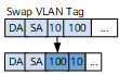
map
An EVC Layer 2 sub-interface with this traffic behavior type maps VLAN tags carried in received packets to other configured tags in one of the following modes:1 to 1: The sub-interface maps a tag in each received single-tagged packet to a specified tag.
1 to 2: The sub-interface maps a tag in each received single-tagged packet to the specified two tags.
2 to 1: The sub-interface maps the outer tag in each received double-tagged packet to a specified tag.
2 to 2: The sub-interface maps two tags in each received double-tagged packet to the two specified tags.
offset: The sub-interface increases or decreases, by a specified offset, the VLAN ID value in a tag carried in each single-tagged packet or in the outer tag carried in each double-tagged packet.
A network needs to be expanded with the growth of access users and data services, which poses the following challenges to network management:- Existing and new sites that are assigned to different VLANs cannot communicate at Layer 2.
- VLAN IDs at various sites accessing a public network may overlap. A public network fails to transmit packets between sites using the same VLAN IDs.
- Two ends of a public network connection support different numbers of tags carried in each packet.
To face these challenges, configure devices on the public network edge to map VLAN tags in access packets to public network VLAN tags. The traffic mapping prevents user VLAN conflicts and helps implement inter-VLAN communication.
Figure 6 map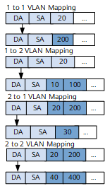
Traffic policies
A traffic policy is a combination of a traffic encapsulation type and a traffic behavior. In the following example, a traffic policy is used. On the network shown in Figure 7, users accessing PE1 need to communicate with users on other PEs at Layer 2. The following steps are performed:- Create a bridge domain on PE1, create an EVC Layer 2 sub-interface on the PE1 interface that users access, configure an encapsulation type on the EVC Layer 2 sub-interface and add the EVC Layer 2 sub-interface to the bridge domain.
- Create a bridge domain with the same ID as that on PE1 on each of the other PEs, configure EVC Layer 2 sub-interfaces on PE interfaces that user access, specify various encapsulation types and behaviors, and add all EVC Layer 2 sub-interfaces to the bridge domain.
- Create EVC Layer 2 sub-interfaces connecting all PEs except PE1 and add these sub-interfaces to the same bridge domain.
All user devices must be on the same network segment to help users on PE1 and other PEs successfully communicate.
Figure 7 Traffic policy applications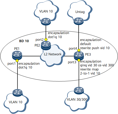
Device Name
Interface Name
Traffic Encapsulation Type
Traffic Behavior
Processing User-to-Device Packets
Processing Device-to-User Packets
PE1
port1
Dot1q
-
Only transparently transmits packets.
Only transparently transmits packets.
PE2
port2
Dot1q
-
Only transparently transmits packets.
Only transparently transmits packets.
PE3
port3
QinQ
map 2-to-1 vid 10
Maps VLAN ID 30 to VLAN ID 10 in the outer tag and leaves the inner tag with VLAN ID 300 in each received double-tagged packet.
Maps the tag with VLAN ID 10 in each received single-tagged packet to the outer tag with VLAN ID 30 and inner tag with VLAN ID 300.
PE3
port4
Default
push vid 10
Adds a tag with VLAN ID 10 to each received untagged packet.
Removes tag with VLAN ID 10 from each received single-tagged packet.
Traffic encapsulation types and behaviors can be combined flexibly in policies. Table 4 describes traffic policies for transmitting traffic.
Table 4 Traffic policies Traffic Behavior
Traffic Encapsulation Type
-
Default
Dot1q
QinQ
Untagged
push 1
Supported
Supported
Supported
Supported
push 2
Not supported
Supported
Not supported
Supported
pop single
Not supported
Supported
Supported
-
pop double
Not supported
-
Supported
-
swap
Not supported
-
Supported
-
1 to 1 map
Not supported
Supported
Supported
-
1 to 2 map
Not supported
Supported
Supported
-
2 to 1 map
Not supported
-
Supported (outer tag)
-
2 to 2 map
Not supported
-
Supported
-
offset
Not supported
Supported
Supported
-
Quality of service (QoS) policies can be deployed on Layer 2 sub-interfaces to differentiate services and properly allocate resources for the services.
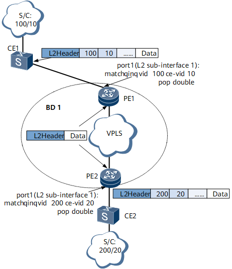
Traffic forwarding
Figure 8 shows traffic forwarding based on an EVC model when Layer 2 sub-interfaces receive packets carrying two VLAN tags.
Layer 2 sub-interfaces are created on the PE1 and PE2 interfaces connecting to the CEs. A traffic policy is deployed on each EVC Layer 2 sub-interface, and the sub-interfaces are added to BD1.
Packet transmission from CE1 to CE2
When receiving double-tagged packets from CE1, the EVC Layer 2 sub-interface of port 1 on PE1 matches the packets against its traffic encapsulation and receives only the packets with the outer VLAN ID 100 and inner VLAN ID 10. The EVC Layer 2 sub-interface removes both VLAN tags from the packets based on its traffic behavior and then forwards the packets to PE2.
Before the EVC Layer 2 sub-interface of port 1 on PE2 forwards the packets to CE2, the sub-interface adds the outer VLAN ID 200 and inner VLAN ID 20 to the packets based on its traffic encapsulation and traffic behavior.
Packet transmission from CE2 to CE1
When receiving double-tagged packets from CE2, the EVC Layer 2 sub-interface of port 1 on PE2 matches the packets against its traffic encapsulation and receives only the packets with the outer VLAN ID 200 and inner VLAN ID 20. The EVC Layer 2 sub-interface removes both VLAN tags from the packets based on its traffic behavior and then forwards the packets to PE1.
Before the EVC Layer 2 sub-interface of port 1 on PE1 forwards the packets to CE1, the sub-interface adds the outer VLAN ID 100 and inner VLAN ID 10 to the packets based on its traffic encapsulation and traffic behavior.
Broadcast Domain
EVC has a unified broadcast domain model, as shown in Figure 9.
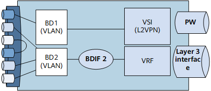
Each BD is a virtual broadcast domain in the EVC model.
Different BDs can carry services from the same VSI, and services are differentiated using BD IDs. BDs are isolated from each other, and MAC address learning is based on BDs, preventing MAC address flapping.
Layer 3 Access
A BDIF interface is created for a BD in the EVC model. A BDIF interface terminates Layer 2 services and provides Layer 3 access. Figure 10 shows how a BDIF interface forwards packets between Layer 2 and Layer 3.
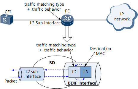
A BD is created on the PE and implements Layer 2 forwarding of packets from the user network. Layer 2 sub-interfaces are created on the user side and bound to the same BD and are each configured with a traffic policy.
A BDIF interface, which is a virtual interface that implements Layer 3 packet forwarding is created based on the BD and assigned an IP address.
When forwarding packets, the BDIF interface matches only the destination MAC address in each packet.
- Layer 2 to Layer 3: When receiving user packets, Layer 2 sub-interfaces process the packets based on the traffic policies and then forward the packets to the BD. If the destination MAC address of a user packet is the MAC address of the BDIF interface, the device removes the Layer 2 header of the packet and performs Layer 3 packet forwarding based on the routing tables. For all other user packets, the device directly performs Layer 2 forwarding for them based on the MAC address table.
- Layer 3 to Layer 2: When receiving packets, the device searches its routing table for the outbound BDIF interface and then sends the packets to this interface. The BDIF interface encapsulates the packets based on the ARP entries. The device then searches its MAC address table for the outbound interfaces and performs Layer 2 forwarding for the packets.