LDP VPWS
Description
LDP VPWS is an MPLS L2VPN technology that establishes point-to-point links to implement L2VPN and uses the LDP signaling to transmit VC information.
LDP VPWS uses double labels for traffic transmission. The inner label is exchanged using extended LDP, and the outer label is a tunnel label.
On an LDP VPWS network, multiple VCs can be established over one LSP between two PEs. In addition, PEs store only a small amount of L2VPN information, such as mappings between VC labels and LSPs. Ps do not store any L2VPN information. Therefore, LDP VPWS has excellent scalability. To add a VC, you only need to configure a unidirectional VC on each endpoint PE. This operation does not affect network operations.
LDP VPWS uses the LDP signaling protocol, being independent from the periodic refresh mechanism. Therefore, LDP VPWS supports fast fault detection.
Basic Concepts
In LDP VPWS, the VC type and VC ID together uniquely identify a VC between CEs.
The VC type indicates the encapsulation type of a VC. The VC type can be Ethernet, or VLAN.
The VC ID identifies a VC. VCs of the same type must have unique IDs on a PE.
The endpoint PEs exchange VC labels using LDP, and each CE is bound to the peer CE according to the VC ID. A VC can be successfully established if the following conditions are all met:
- The physical status of AC interfaces is up.
- The tunnel between the PEs has been established.
- Labels have been exchanged between two PEs and the CE binding have been completed.
In LDP VPWS, the outer label is used to transmit the data of each VC over an ISP network, and the inner VC label is used to identify the type of service data. In light of this, an LSP on the ISP network can be shared by multiple VCs.
To support LDP VPWS, an ISP network must be able to automatically establish LSPs. This means that the ISP network must support MPLS forwarding and MPLS LDP.
LDP VPWS Network Topology
Figure 1 shows the LDP VPWS network topology.
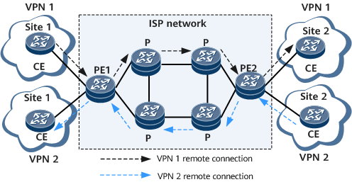
As shown in Figure 1, site 1 and site 2 of VPN 1 are connected over a remote LDP connection (as indicated by the black dashed line). Site 1 and site 2 of VPN 2 are also connected over a remote LDP connection (as indicated by the blue dashed line). Either one or two LSPs can be established within the ISP network for communication between VPN 1 and VPN 2.
PWE3 VPWS
LDP VPWS is classified into PWE3-compatible VPWS and PWE3 VPWS.
- PWE3-compatible VPWS: does not use Notification messages.
- PWE3 VPWS: uses Notification messages.
PWE3 simulates the basic behaviors and characteristics of services, such as ATM, Ethernet, low-speed TDM circuit, and SONET/SDH, on a PSN to transmit Layer 2 traffic.
PWE3 is a type of VLL implementation and an extension to the LDP protocol. By extending the LDP signaling, reducing the signaling cost, and defining the multi-segment negotiation mode, PWE3 improves networking flexibility. Compared with LDP VPWS, PWE3 VPWS exchanges fewer packets when the network is unstable, preventing repeated PW establishment and deletion.
- PWE3 networking modes
Single-segment PWE3 networking
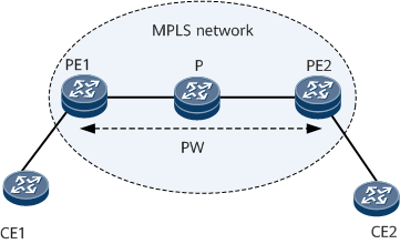
Single-segment PWE3 means that only one PW exists between two PEs, and no inner label swapping is needed. Because the PW uses LDP as a signaling protocol to transmit VC information, an LDP session must be established between the PEs:If Ps exist between the PEs, a remote LDP session must be created.
If the PEs are directly connected, a local LDP session can be created.
Figure 2 shows the typical single-segment PWE3 networking with a PW established using LDP signaling.
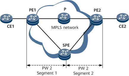
Multi-segment PWE3 networking
An MS-PW is a set of two or more PW segments between two PEs. The MS-PW forwarding mechanism is the same as the SS-PW forwarding mechanism on PEs. The only difference is that PW labels are swapped on switching PEs (SPEs) for MS-PWs. Figure 3 shows the typical multi-segment PWE3 networking.
If two PEs cannot establish a connection using signaling or cannot establish a direct tunnel, configure an MS-PW between the two PEs. Supporting PWE3 MS-PWs improves networking flexibility.
Besides being classified into SS-PWs and MS-PWs, PWs can also be classified into static and dynamic PWs. The two types of PWs can be used together. For example, an MS-PW can be a set of static and dynamic PW segments.
Dynamic PW
Dynamic PWs are established using signaling protocols. UPEs swap VC labels using LDP and bind the corresponding CEs to AC interfaces based on VC IDs. A VC is established when all the following conditions are satisfied: two PEs have established a tunnel; the two PEs have exchanged VC labels and bound the VC ID to corresponding CEs; the ACs of the two PEs are up.
Messages used by a dynamic PW include:
Request: requests a peer PE to allocate labels.
Mapping: notifies a peer PE of a label allocated by a local PE. Whether the Label Mapping message carries the Status field depends on the default signaling. By default, LDP VPWS does not support the Status field.
Notification: advertises and negotiates the PW status, reducing the number of messages to be exchanged.
Withdraw: carries label and status information to instruct the peer PE to withdraw labels.
Release: responds to a Label Withdraw message, and notifies the peer that sends the Label Withdraw message of the label release event.
Establishment, Maintenance, and Deletion of Dynamic PWs
Dynamic PWs are established using LDP, whose TLV is extended to carry VC information. Before a dynamic PW is established between two PEs, an LDP session must be established between the two PEs. During the establishment of a dynamic PW, the label distribution control mode is downstream unsolicited (DU) and the label retention mode is liberal.

If Ps exist between the two PEs, a remote LDP session can be established. If the two PEs are directly connected, a local LDP session can be established.
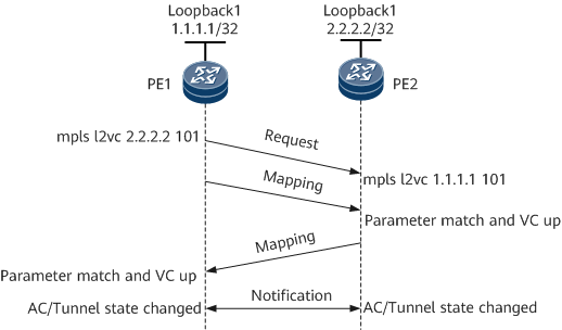
After PWE3 is configured on the two PEs and an LDP session is established between the two PEs, the dynamic PW starts to be established. Figure 4 shows the process of establishing a dynamic PW.
PE1 sends a Label Request message and a Label Mapping message to PE2.
After receiving the Label Request message from PE1, PE2 sends a Label Mapping message to PE1.
After receiving the Label Mapping message from PE1, PE2 determines whether the configuration of a PW is consistent with that on PE1. If its PW configurations such as the VC ID, VC type, MTU, and control word (CW) enabling status are consistent with those on PE1 after negotiation, PE2 sets the PW status to up.
After receiving the Label Mapping message from PE2, PE1 determines whether its PW configurations are consistent with those on PE2 after negotiation. If the parameters are consistent, PE1 sets the PW status to up. After that, a dynamic PW is established between PE1 and PE2.
After the dynamic PW is established, PE1 and PE2 learn the status of each other by exchanging Notification messages.
If the AC interface of a PW is down or the corresponding tunnel is down, PWE3-compatible VPWS and PWE3 VPWS use different processing mechanisms:
- In PWE3-compatible mode, the local PE sends a Label Withdraw message to its peer to tear down the PW. After the AC interface or tunnel goes up, another round of negotiation is required for the PEs to establish a PW.
- In PWE3 mode, the local PE sends a Notification message to notify its peer that data packets cannot be forwarded, but the PW is not torn down. After the AC interface or tunnel goes up, the local PE sends a Notification message to notify its peer that data packets can be forwarded.
A PW is torn down only when PW configurations are deleted from the PEs or when the LDP session is interrupted. Using Notification messages prevents repeated PW establishment and deletion caused by link flapping.
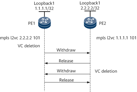
Figure 5 shows the process of tearing down a PW.
When PW configurations are deleted from PE1, PE1 withdraws its VC label and sends Label Withdraw and Label Release messages to PE2 in succession.
- After receiving the Label Withdraw message from PE1, PE2 withdraws its VC label and sends a Label Release message to PE1.
- After PE1 and PE2 receive the Label Release message from each other, PE1 and PE2 have deleted the PW.
The Label Withdraw message instructs a PE to withdraw the PW label. The Label Release message is a response to the Label Withdraw message to inform the PE sending the Label Withdraw message that the PW label has been withdrawn on the peer. To tear down the PW more quickly, PE1 can send the Label Withdraw and Label Release messages in succession.
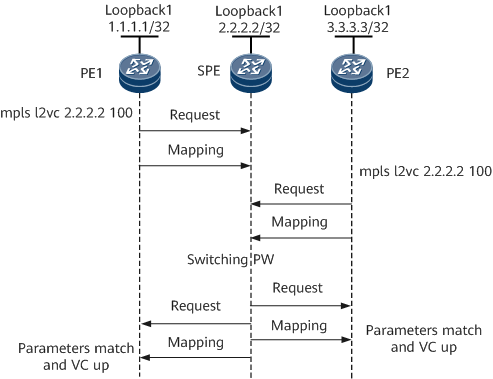
The difference between an SS-PW and an MS-PW is that one or more SPEs exist between the endpoint PEs of an MS-PW. Figure 6 shows an example of the signaling interaction process for an MS-PW between PE1 and PE2. The SPE connects the two PW segments that are established to PE1 and PE2.
During signaling negotiation, the SPE forwards to PE2 the parameters carried in the Label Mapping message sent by PE1 and forwards to PE1 the parameters carried in the Label Mapping message sent by PE2. If these parameters are consistent through negotiation, the PW status becomes up. Similar to Label mapping messages, Label Release, Withdraw, and Notification messages are forwarded segment by segment.
Extensions on the PWE3 control plan
Signaling extension
The means of sending a Notification message is added to the LDP signaling, which is merely to advertise the status but will not tear down a signaling connection. A signaling disconnection occurs only when the PW configurations are deleted or the signaling is interrupted. This signaling extension allows for fewer control packet exchanges, reduces the signaling cost, and is compatible with the original LDP mode.
Other extensions
Other extensions on the control plane are as follows:
Mechanism for negotiating fragmentation
PW connectivity detection, such as virtual circuit connectivity verification (VCCV), is added, improving the fast network convergence capability and network reliability.
Extensions on the PWE3 data plane
Real-time information extension
Bandwidth, jitter, and delay assurance of electrical signals
Retransmission of disordered packets