Application of EVC Bearing VPLS Services
Service Overview
As enterprises widen their global reach and establish more branches in different regions, applications such as instant messaging and teleconferencing are becoming more common. This imposes high requirements for end-to-end (E2E) Datacom technologies. A network capable of providing point to multipoint (P2MP) and multipoint to multipoint (MP2MP) services is paramount to Datacom function implementation. To ensure the security of enterprise data, secure, reliable, and transparent data channels must be provided for multipoint transmission.
Generally, enterprises lease virtual switching instances (VSIs) on a carrier network to carry services between branches.
Networking Description
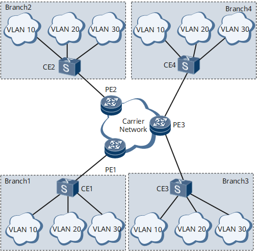
In Figure 1, Branch 1 and Branch 3 belong to one department (the Procurement department, for example), and Branch 2 and Branch 4 belong to another department (the R&D department, for example). Services must be isolated between these departments, but each department can plan their VLANs independently (for example, different service development teams belong to different VLANs). The enterprise plans to dynamically adjust the departments but does not want to lease multiple VSIs on the carrier network because of the associated costs.
Feature Deployment
In the traditional service model supported by the NetEngine 8000 F shown in Figure 1, common sub-interfaces (VLAN type), sub-interfaces for dot1q VLAN tag termination, or sub-interfaces for QinQ VLAN tag termination are created on the user-side interfaces of the PEs. These sub-interfaces are bound to different VSIs on the carrier network to isolate services in different departments. If the enterprise sets up another department, the enterprise must lease another VSI from the carrier to isolate the departments, increasing costs.
To allow the enterprise to dynamically adjust its departments and reduce costs, the EVC model can be deployed on the PEs. In the EVC model, multiple BDs are connected to the same VSI, and the BDs are isolated from each other.
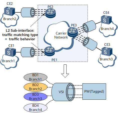
- VPLS connections are created on the PEs to ensure communication on the Layer 2 network.
- BDs are created on the PEs to isolate enterprise services.
EVC Layer 2 sub-interfaces are created on the PEs on the user side, are configured with QinQ traffic encapsulation type and pop double traffic behavior, and transmit Enterprise services to the carrier network.
- A BDIF interface is created in each BD, and the BDs are bound to the same VSI to transmit enterprise services over pseudo wires (pws) in tagged mode.
- When a packet travels from a BD to a PW, the PE adds the BD ID to the packet as the outer tag (P-Tag).
- When a packet travels from a PW to a BD, the PE searches for the VSI instance based on the VC label and the BD based on the P-Tag.
The NetEngine 8000 F also supports the exclusive VSI service mode. This mode is similar to a traditional service mode in which sub-interfaces are bound to different VSIs to connect to the VPLS network. Figure 3 shows a diagram of the exclusive VSI service mode.
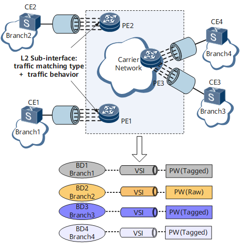
In the exclusive VSI service mode, each VSI is connected to only one BD, and the BD occupies the VSI resource exclusively.