LDP VPLS
Background
LDP VPLS uses a static discovery mechanism to discover VPLS members using LDP signaling. VPLS information is carried in extended TLV fields (type 128 and type 129 FEC TLVs) of LDP signaling packets. Here, FEC stands for forwarding equivalence class. During the establishment of a PW, the label distribution mode is downstream unsolicited (DU) and the label retention mode is liberal.
Related Concepts
LDP VPLS involves the following concepts:
FEC: A set of packets with similar or identical characteristics and forwarded in the same way by LSRs. Characteristics determining the FEC of a packet include the destination address, service type, and QoS attribute.
TLV: A highly efficient and expansible coding mode for protocol packets. To support new features, you only need to add new types of TLVs to carry information required by the features.
DU: A label distribution mode in which a label switching router (LSR) distributes labels to FECs without having to receive Label Request messages from its upstream LSR.
Liberal: A label retention mode in which an LSR retains the label mapping received from a neighboring LSR, regardless of whether the neighboring LSR is its next hop. In liberal label retention mode, an LSR can use the labels sent from neighboring LSRs that are not at the next hop to re-establish an LSP. This mode requires more memory and label space than the conservative mode.
Implementation Process
Figure 1 shows the process of establishing a PW using LDP signaling.
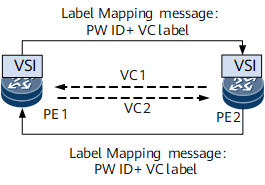
- After PE1 is associated with a VSI, and PE2 is configured as a peer of PE1, PE1 sends a Label Mapping message to PE2 in DU mode if an LDP session exists between PE1 and PE2. The Label Mapping message carries information required to establish a PW, such as the PW ID, VC label, and interface parameters.
- Upon receipt, PE2 checks whether itself has been associated with the VSI. If PE2 has been associated with the VSI and PW parameters on PE1 and PE2 are consistent, PE1 and PE2 belong to the same VSI. In this case, PE2 establishes a unidirectional VC named VC1 immediately after PE2 receives the Label Mapping message. Meanwhile, PE2 sends a Label Mapping message to PE1. After receiving the message, PE1 takes a sequence of actions similar to those taken by PE2 and establishes VC2.
Figure 2 shows the process of tearing down a PW using LDP signaling.
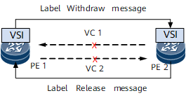
- After the peer configuration about PE2 is deleted from PE1, PE1 sends a Label Withdraw message to PE2. After receiving the Label Withdraw message, PE2 withdraws its local VC label, tears down VC1, and sends a Label Release message to PE1.
- After receiving the Label Release message, PE1 withdraws its local VC label and tears down VC2.
Derivative Functions
MAC Withdraw Loop Detection
On a dual-homing VPLS or hierarchical VPLS (HVPLS) network, data packets and MAC Withdraw messages can be forwarded between hub and spoke PWs and between spoke PWs. If hub or spoke PWs are not configured correctly, a data packet or MAC Withdraw message loop may occur. Techniques, such as Virtual Router Redundancy Protocol (VRRP), Spanning Tree Protocol (STP), and MAC flapping, can be used to prevent a data packet loop. MAC Withdraw loop detection prevents a MAC Withdraw message loop. MAC Withdraw loop detection enables a PE to add the Path TLV field to a MAC Withdraw message before the message is forwarded. The Path TLV field records the forwarding path of the message. Figure 3 shows MAC Withdraw loop detection. The rules for a PE to forward a MAC Withdraw message are as follows:
When a PE forwards a MAC Withdraw message, the PE adds its own LSR ID to the Path TLV field carried in the message.
After the PE receives the message, it checks whether the message includes its own LSR ID and whether the number of LSR IDs carried in the Path TLV field exceeds 255. If the message includes its own LSR ID or the number of LSR IDs carried in the Path TLV field exceeds 255, the PE immediately discards the message.

After you configure MAC Withdraw loop detection on a PE, the PE adds the Path TLV field to a MAC Withdraw message before forwarding the message. If a PE is not configured with MAC Withdraw loop detection, the PE directly forwards the MAC Withdraw message that it receives.

Receiving of Group Messages by PWs
The IETF defines the usage scenario of this function. If multiple PWs, belonging to the same group and having the same status, are configured on a physical interface, group messages can be used to notify PWs of the interface status change when the physical interface goes Up or Down, reducing the number of Notification messages required.
PW Reliability
LDP VPLS ensures PW reliability using the following mechanisms:
- Association between VPLS and management Virtual Router Redundancy Protocol (mVRRP): In the IP radio access network (RAN) solution, after a cell site gateway (CSG) obtains the active/standby device status information from an mVRRP group, it determines the primary/secondary status of PWs itself.
- Manual configuration: LDP VPLS allows the primary/secondary status of PWs to be configured manually.
Usage Scenario
The LDP mode applies to VPLS networks that do not have many sites, do not span multiple ASs, or with PEs that do not run BGP.
Benefits
LDP VPLS offers the following benefits:
- Easy configuration
- Label resource saving