IGMP Snooping
Background
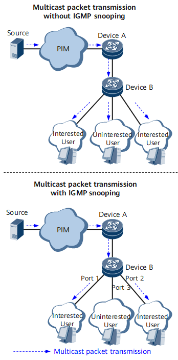
Layer 3 devices and hosts use IGMP to implement multicast data communication. IGMP messages are encapsulated in IP packets. A Layer 2 device can neither process Layer 3 information nor learn multicast MAC addresses in link layer data frames because source MAC addresses in data frames are not multicast MAC addresses. As a result, when a Layer 2 device receives a data frame in which the destination MAC address is a multicast MAC address, the device cannot find a matching entry in its MAC address table. The Layer 2 device then broadcasts the multicast packet, which wastes bandwidth resources and compromises network security.
IGMP snooping addresses this problem by controlling multicast traffic forwarding at Layer 2. IGMP snooping enables a Layer 2 device to listen to and analyze IGMP messages exchanged between a Layer 3 device and hosts. Based on the learned IGMP message information, the device creates a Layer 2 forwarding table and uses it to implement on-demand packet forwarding.
- If Device B does not run IGMP snooping, Device B broadcasts all received multicast data at the data link layer.
- If Device B runs IGMP snooping and receives data for a multicast group, Device B searches the Layer 2 multicast forwarding table for ports connected to the users who require the data. In this example, Device B sends the data only to Port 1 and Port 2 because the user connected to Port 3 does not require the data.
| Multicast Group | Downstream Port |
|---|---|
| 225.0.0.1 | Port 1 |
| 225.0.0.1 | Port 2 |
Related Concepts
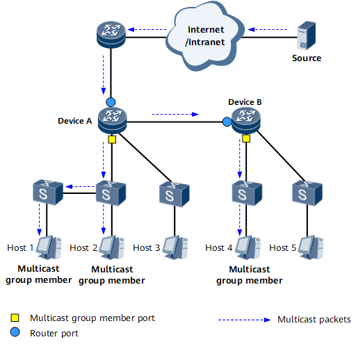
A router port (labeled with a blue circle in Figure 2): It connects a Layer 2 multicast device to an upstream multicast router.
Router ports can be dynamically discovered by IGMP or manually configured.
A member port of a multicast group (labeled with a yellow square in Figure 2): It connects a Layer 2 multicast device to group member hosts and is used by a Layer 2 multicast device to send multicast packets to hosts.
Member ports can be dynamically discovered by IGMP or manually configured.
- A Layer 2 multicast forwarding entry: It is stored in the multicast forwarding table and used by a Layer 2 multicast device to determine the forwarding of a multicast packet sent from an upstream device. Information in a Layer 2 multicast forwarding entry includes:
VLAN ID or VSI name
Multicast group address
Router port that connects to an upstream device
Member port that connects to a host
Multicast MAC address: It is mapped from a multicast IP address contained in a multicast data packet at the data link layer. Multicast MAC addresses are used to determine multicast data packet forwarding at the data link layer.
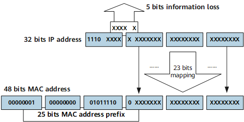
As defined by the Internet Assigned Numbers Authority (IANA), the 24 most significant bits of a multicast MAC address are 0x01005e, the 25th bit is 0, and the 23 least significant bits are the same as those of a multicast IP address.
Figure 3 shows the mapping between a multicast IP address and a multicast MAC address. For example, if the IP address of a multicast group is 224.0.1.1, the MAC address of this multicast group is 01-00-5e-00-01-01. Information about 5 bits of the IP address is lost, because only 23 bits of the 28 least significant bits of the IP address are mapped to the MAC address. As a result, 32 IPv4 multicast addresses are mapped to the same MAC address. In this example, IP multicast addresses 224.0.1.1, 224.128.1.1, 225.0.1.1, and 239.128.1.1 all correspond to the multicast MAC address 01-00-5e-00-01-01.
Implementation
IGMP snooping is implemented as follows:
After IGMP snooping is deployed on a Layer 2 device, the device uses IGMP snooping to analyze IGMP messages exchanged between hosts and a Layer 3 device and then creates a Layer 2 multicast forwarding table based on the analysis. Information in forwarding entries includes VLAN IDs or VSI names, multicast source addresses, multicast group addresses, and numbers of ports connected to hosts.
- After receiving an IGMP Query message from an upstream device, the Layer 2 device sets a network-side port as a dynamic router port.
- After receiving a PIM Hello message from an upstream device, the Layer 2 device sets a network-side port as a dynamic router port.
- After receiving an IGMP Report message from a downstream device or user, the Layer 2 device sets a user-side port as a dynamic member port.
- The IGMP snooping-capable Layer 2 device forwards a received packet based on the Layer 2 multicast forwarding table.
Other Functions
IGMP snooping supports all IGMP versions.
IGMP has three versions: IGMPv1, IGMPv2, and IGMPv3. You can specify an IGMP version for your device.
IGMP snooping enables a Layer 2 device to rapidly respond to Layer 2 network topology changes.
Multiple Spanning Tree Protocol (MSTP) is usually used to connect Layer 2 devices to implement rapid convergence. IGMP snooping adapts to this feature by enabling a Layer 2 device to immediately update port information and switch multicast data traffic over a new forwarding path when the network topology changes, which minimizes multicast service interruptions.
IGMP snooping allows you to configure a security policy for multicast groups.
This function can be used to limit the range and number of multicast groups that users can join and to determine whether to receive multicast data packets containing a security field. It provides refined control over multicast groups and improves network security.
Deployment Scenarios
IGMP snooping can be used on VLANs and virtual private LAN service (VPLS) networks.
Benefits
IGMP snooping deployed on a user-side router offers the following benefits:
Reduced bandwidth consumption
Independent accounting for individual hosts