VPWS Basic Functions
Basic VPWS Architecture
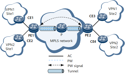
As shown in Figure 1, the VPWS architecture consists of ACs, PWs, and tunnels.
Functional Modules
VPWS has the following functional modules:
AC: An independent physical or virtual circuit connecting a CE and a PE. An AC interface can be a physical interface or a virtual interface. The AC attributes include the encapsulation type, maximum transmission unit (MTU), and interface parameters of the specified link type.
PW: A virtual link or path between two nodes on a network. In this document, it is a virtual connection between two PEs.
Tunnel: A virtual link used to transparently transmit service data.
PW signaling: A type of signaling for PW negotiation.
Figure 1 uses the flow direction of VPN1 packets from CE1 to CE3 as an example to show data transmission.
CE1 sends user packets to PE1 over an AC.
Upon receipt, PE1 selects a PW to forward the packets.
PE1 generates double MPLS labels (one VPN label and one public network label) according to the PW forwarding entry. The VPN label identifies a PW, and the public network label identifies a public network tunnel.
After user packets travel along the public network tunnel to PE2, PE2 removes the VPN label. The public network label is removed by means of penultimate hop popping (PHP) on the P.
PE2 selects an AC and forwards these packets to CE3.
Figure 2 shows label changes in packet forwarding over a VPWS network.
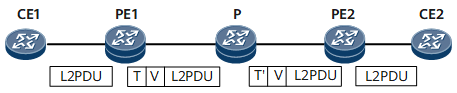
In Figure 2:
L2PDU: Layer 2 protocol data unit, a type of link-layer packet.
T: a tunnel label.
V: a virtual circuit (VC) label.
T': a substitute tunnel label during packet forwarding.