Intra-VLAN Proxy ARP Application
Networking Description
As shown in Figure 1, to facilitate ease of management, communication isolation is implemented for various departments on the intranet of a company. For example, although Host A of the president's office, Host B of the R&D department, and Host C of the financial department belong to the same VLAN, they cannot communicate at Layer 2. However, the business requires that the president's office communicate with the financial department. To permit this, enable intra-VLAN proxy ARP on the CE so that Host A can communicate with Host C.
Before intra-VLAN proxy ARP is enabled, if Host A sends an ARP request message for the MAC address of Host C, the message cannot be broadcast to hosts of the R&D department and financial department because port isolation is configured on the CE. Therefore, Host A can never learn the MAC address of Host C and cannot communicate with Host C.
After intra-VLAN proxy ARP is enabled, the CE does not discard the ARP request message sent from Host A even if the destination IP address in the message is not its own IP address. Instead, the CE sends the MAC address of its VLANIF4 to Host A. Host A then sends IP datagrams to this MAC address.
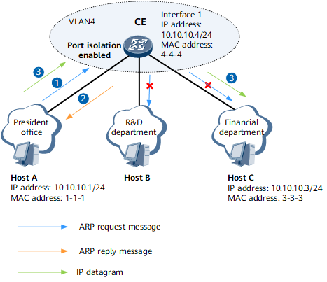

The type of interface 1 could be dot1q termination sub-interface or VLANIF interface.
Feature Deployment
Configure interface 1, which is a Layer 3 interface, on the CE, and enable intra-VLAN proxy ARP. After the deployment, the CE sends the MAC address of its interface 1 to Host A when receiving a request for the MAC address of Host C from Host A. Host A then sends IP datagrams to the CE, which forwards the IP datagrams to Host C. Consequently, the communication between Host A and Host C is implemented.