Application of MCEs on a Campus Network
Networking Description
BGP/MPLS IP VPN, which can isolate users on a campus network, is complicated to deploy and expensive to maintain. Since the number of users to be isolated on a campus network is small, you can use the MCE multi-hop technology instead.
Simplified configuration
MPLS or MP-BGP does not need to be configured.
Reduced costs
PEs and Ps do not need to be deployed.
Feature Deployment
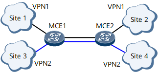
The link between MCE1 and MCE2 is bound to a VPN and a routing protocol is configured on both ends of the link.
Each link between an MCE and a site is bound to a VPN and a routing protocol is configured on both ends of these links.
The route import function is configured on MCEs, if the routing protocol running between MCEs and sites is different than that running between the MCEs.
Route Transmission
Site 1 sends its VPN routes to MCE1. Upon receipt, MCE1 adds these routes to its VPN routing and forwarding table.
MCE1 sends received routes to MCE2.
Upon receipt, MCE2 determines whether the export RTs of these routes match its import RTs. If yes, MCE2 adds these routes to its VPN routing and forwarding table and sends them to Site 2.
Packet Forwarding
Site 2 sends a packet destined for Site 1 to MCE2 after searching its local routing and forwarding table.
Upon receipt, MCE2 searches the corresponding VPN routing and forwarding table based on the inbound interface of the packet and forwards the packet to MCE1.
Upon receipt, MCE1 searches the corresponding VPN routing and forwarding table based on the inbound interface of the packet and forwards the packet to Site 1.
Upon receipt, Site 1 checks the destination address of the packet and processes this packet normally after finding that the destination address is itself.