HSI Service Bearer Using PWE3
Service Overview
High speed Internet (HSI) services are provided over IP networks.
As shown in Figure 1,
users access the broadband remote access server (BRAS) by means of
Ethernet access. Usually:
- DSLAMs are far away from a BRAS, and an intermediate network is required to connect them.
- Large numbers of DSLAMs are deployed on a network, but the number of DSLAMs for which each BRAS can provide access services is limited and a BRAS is expensive.
HSI services are data services that do not require low delays. Access and bearer networks can meet the following requirements:
- Strong expansibility
- Clear management responsibilities
- Effective control on Layer 2 broadcast domains
- Guaranteed user data security
- Support for multiple protocols and smooth network upgrade
- Convenient configuration
Networking Description
In Figure 1, digital subscriber line access multiplexers (DSLAMs) converge HSI service packets to UPEs through VLANs. The UPEs transmit the packets to the NPE through PWs. After receiving the packets, the NPE removes PW labels, adds VLAN tags to the packets, and transmits the packets to the BRAS. The BRAS removes the VLAN tags. HSI service users dynamically access the BRAS by means of Ethernet access to obtain IP addresses.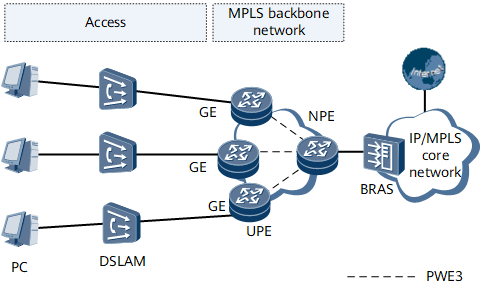
Feature Deployment
- IP addresses and IGPs are configured on the carrier's MPLS backbone network for communication between PEs.
- MPLS is enabled on the carrier's backbone network. TE tunnels are configured between UPEs and NPEs. Usually, two TE tunnels are configured between each UPE and NPE, one as the primary tunnel and the other as the backup tunnel.
- MPLS L2VPN is enabled on each UPE and NPE. A remote MPLS LDP session is configured between each UPE and NPE.
- PWE3 is configured on AC interfaces of each UPE and NPE, so that UPEs and NPEs can communicate over MPLS L2VCs.