OSPFv3 IP FRR
OSPFv3 IP fast reroute (FRR) is dynamic IP FRR, and refers to the process by which OSPFv3 precomputes a backup path based on the network-wide LSDBs, and stores this backup path in the forwarding table. If the primary path fails, traffic can be quickly switched to the backup path.
OSPFv3 IP FRR complies with standard protocols. With OSPFv3 IP FRR, devices can switch traffic from a faulty primary link to a backup link, protecting against a link or node failure.
Background
As networks develop, Voice over Internet Protocol (VoIP) and online video services pose higher requirements for real-time transmission. Nevertheless, if a primary link fails, OSPFv3-enabled devices need to perform multiple operations, including detecting the fault, updating the link-state advertisement (LSA), flooding the LSA, calculating routes, and delivering forward information base (FIB) entries before switching traffic to a new link. This process takes a much longer time than the minimum delay to which users are sensitive. As a result, the requirements for real-time transmission cannot be met.
Implementation
OSPFv3 IP FRR refers to a mechanism in which a device uses the loop-free alternate (LFA) algorithm to precompute the next hop of a backup route, and stores the primary and backup routes to the same destination address but with different next hops in the forwarding table. If the primary link fails, the device switches traffic to the backup link before route convergence is complete on the control plane. This mechanism minimizes the length of traffic interruptions and protects services. The NetEngine 8000 F supports OSPFv3 IP FRR.
A device uses the shortest path first (SPF) algorithm to calculate the shortest path from each neighbor that can provide a backup link to the destination node. The device then uses the inequalities defined in standard protocols and the LFA algorithm to calculate the next hop of the loop-free backup link that has the smallest cost of the available shortest paths.
An OSPFv3 IP FRR policy is used to filter alternate next hops. Only the alternate next hops that match the filtering rules of the policy can be added to the IP routing table. Users can configure a desired OSPFv3 IP FRR to filter alternate next hops.
If a Bidirectional Forwarding Detection (BFD) session is bound to OSPFv3 IP FRR, the BFD session goes down if BFD detects a link fault. If the BFD session goes down, OSPFv3 IP FRR is triggered on the interface to switch traffic from the faulty link to the backup link, which minimizes the loss of traffic.
Usage Scenario
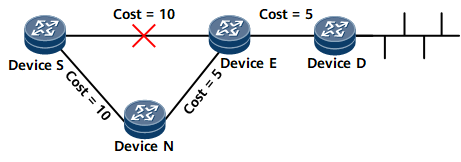
- Link protection: Link protection takes effect when the traffic to be protected flows along a specified link and the link costs meet the inequality: Distance_opt (N, D) < Distance_opt (N, S) + Distance_opt (S, D).
- S: source node
- N: node along a backup link
- D: destination node
On the network shown in Figure 1, traffic is forwarded from DeviceS to DeviceD. The primary link is DeviceS -> DeviceE -> DeviceD, and the backup link is DeviceS -> DeviceN -> DeviceE -> DeviceD. The link costs satisfy the link protection inequality. If the primary link fails, DeviceS switches the traffic to the backup link, minimizing the traffic interruption duration.
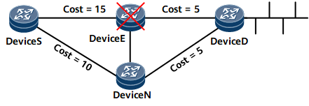
Link-and-node protection: Node-and-link protection takes effect when the traffic to be protected flows along a specified link and node. Figure 2 shows the networking for link-and-node protection. The link-and-node protection takes precedence over the link protection.
Link-and-node protection must satisfy the following conditions:
- The link cost must satisfy the inequality: Distance_opt (N, D) < Distance_opt (N, S) + Distance_opt (S, D).
The interface cost must satisfy the inequality: Distance_opt (N, D) < Distance_opt (N, E) + Distance_opt (E, D).
S indicates the source node of traffic, E indicates the faulty node, N indicates the node on the backup link, and D indicates the destination node of traffic.
OSPFv3 FRR in the Scenario Where Multiple Nodes Advertise the Same Route
OSPFv3 IP FRR uses the SPF algorithm to calculate the shortest path from each neighbor (root node) that provides a backup link to the destination node and store the node-based backup next hop, which applies to single-node routing scenarios. As networks are increasingly diversified, two ABRs or ASBRs are deployed to improve network reliability. In this case, OSPFv3 FRR in a scenario where multiple nodes advertise the same route is needed.

In a scenario where multiple nodes advertise the same route, OSPFv3 FRR is implemented by calculating the Type 3 LSAs advertised by ABRs of an area for intra-area, inter-area, ASE routing. Inter-area routing is used as an example to describe how OSPFv3 FRR works in a scenario where multiple nodes advertise the same route.
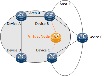
In Figure 3, Device B and Device C function as ABRs to forward routes between area 0 and area 1. Device E advertises an intra-area route. Upon receipt of the route, Device B and Device C translate it to a Type 3 LSA and flood the LSA to area 0. After OSPFv3 FRR is enabled on Device A, Device A considers both Device B and Device C as its neighbors. Without a fixed neighbor as the root node, Device A fails to calculate the FRR backup next hop. To address this problem, a virtual node is simulated between Device B and Device C and used as the root node of Device A, and Device A uses the LFA algorithm to calculate the backup next hop. This solution converts multi-node routing into single-node routing.
For example, both Device B and Device C advertise the route 2001:DB8:1::1/64, and OSPFv3 FRR is enabled on Device A. After Device A receives the route, it fails to calculate a backup next hop for the route due to a lack of a fixed root node. To address this problem, a virtual node is simulated between Device B and Device C and used as the root node of Device A. The virtual node forms a link with each of Device B and Device C. If the virtual node advertises a 2001:DB8:1::1/64 route, it will use the smaller cost of the routes advertised by Device B and Device C as the cost of the route. If the cost of the route advertised by Device B is 5 and that of the route advertised by Device C is 10, the cost of the route advertised by the virtual node is 5. The cost of the link from Device B to the virtual node is 0, and that of the link from Device C to the virtual node is 5. The costs of the links from the virtual node to Device B and Device C are both 65535, the maximum value. Device A is configured to consider Device B and Device C as invalid sources of the 2001:DB8:1::1/64 route and use the LFA algorithm to calculate the backup next hop for the route, with the virtual node as the root node.