MPLS Forwarding
MPLS Forwarding Concepts
Tunnel ID
The system automatically allocates an ID to each tunnel. A tunnel ID uniquely identifies a tunnel interface for a specific upper layer application, such as VPN or route management.
The tunnel ID is 32 bits long. Each field contained in a tunnel ID varies depending on the tunnel type.
Figure 1 shows the tunnel ID structure.
Table 1 Fields in a tunnel ID Field
Description
Token
An index used to search an MPLS forwarding table for a specific entry
Sequence Number
Sequence number of the tunnel ID
Slot Number
Slot ID of an outbound interface that sends packets
Allocation Method
Method used to allocate tokens:Global: All tunnels on a node share the public global token space. Each token must have a unique value.
Global with reserved tokens: Similar to the global method except that some tokens are reserved. Tunnels can only be established using unreserved tokens.
Per slot: Each slot uses its own tokens, which with a unique value. The tokens in one slot may have the same values as those in other slot.
Per slot with reserved tokens: Similar to the per slot method except that some tokens are reserved. Tunnels can only be established using unreserved tokens.
Per slot with different avail value: Similar to the per slot method except that a specific token range is allocated to each slot.
- Mixed: Label spaces are created using both global and per slot methods but takes effect based on the interface type:
- The interfaces of a backbone network or VLANIF interfaces use the label space created using the global method.
- Other interfaces use the label space created using the per slot method.
Mixed with 2 global space: Label spaces are created using the global, global with reserved tokens, and per slot methods. Only one label space takes effect.
2 global space: Label spaces are created using the global and global with reserved tokens methods.
Next hop label forwarding entry (NHLFE)
An NHLFE is used to guide the MPLS packet forwarding.
It contains the following information:
Tunnel ID
Outbound interface name
Next hop address
Outgoing label value
Label operation
Incoming label map (ILM)
An ILM entry defines the mapping between an incoming label and a set of NHLFEs.
An ILM entry contains the following information:
Tunnel ID
Incoming label value
Inbound interface name
Label operation
A transit node creates ILM entries containing the mapping between labels and NHLFEs. The node searches an ILM table for an entry that matches a specific destination IP address before forwarding the packet.
FEC-to-NHLFE (FTN) map
An FTN entry defines the mapping between a FEC and a set of NHLFEs.
The FTN entry is only available on the ingress. You can obtain FTN information by searching for non-0x0 token values in a FIB.

MPLS Forwarding Process
In the following example, a PHP-capable LSP is established to forward MPLS packets.
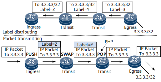
An LSP for a FEC with the destination address 3.3.3.3/32 is established on the MPLS network shown in Figure 2.
The process of forwarding MPLS packets is as follows:
The ingress receives an IP packet destined for 3.3.3.3/32. The ingress adds Label Z to the packet and forwards the packet to the adjacent transit node.
The transit node receives the labeled packet and swaps Label Z for Label Y in the packet. It then forwards the packet to the penultimate transit node.
The penultimate transit node receives the packet with Label Y. As the egress assigns Label 3 to the transit node, the transit node removes Label Y and forwards the IP packet to the egress.
The egress receives the IP packet and forwards it to 3.3.3.3/32.
MPLS Processing on Each Node
When an IP packet enters an MPLS domain, the ingress searches the FIB and checks whether the tunnel ID mapped to the destination IP address is 0x0.
If the tunnel ID is 0x0, the packet is forwarded along the IP link.
If the tunnel ID is not 0x0, the packet is forwarded along an LSP.
Figure 3 shows the MPLS forwarding flow.

Nodes along an LSP search the following tables for entries used to forward MPLS packets:
The ingress searches the FIB and NHLFE tables to forward MPLS packets.
The transit searches the ILM and NHLFE tables to forward MPLS packets.
The egress searches the ILM table to forward MPLS packets.
FIB entries, ILM entries, and NHLFEs of the same tunnel have the same token values.
The ingress performs the following steps:
Searches the FIB table and finds a tunnel ID mapped to a specific destination IP address.
Finds an NHLFE mapped to the tunnel ID in the FIB table and associates the FIB entry with the NHLFE.
Checks the NHLFE for the outbound interface name, next hop address, outgoing label value, and label operation. The label operation type is Push.
Pushes a label into an IP packet, processes the EXP field based on a specific QoS policy and TTL field, and sends the encapsulated MPLS packet to the transit node.
A transit node performs the following steps:
Searches the ILM table for a token that matches the MPLS label.
Searches for the NHLFE that maps to the token.
- Checks the NHLFE for the outbound interface name, next hop address, outgoing label value, and label operation.
- If the label is greater than or equal to 16, the label operation is Swap.
- If the label is 3, the label operation is Pop.
Processes MPLS packets based on the label value:
- If the label value is greater than or equal to 16, the transit node performs the following operations:
- Replaces the existing label with a new label in the MPLS packet.
- Reduces the EXP value and TTL value by 1.
- Forwards the MPLS packet with the new label to the egress.
- If the label value is 3, the transit node performs the following operations:
- Removes the label from the MPLS packet.
- Reduces the EXP value and TTL value by 1.
- Forwards the IP packet over an IP route or to a next hop based on another label.
The egress performs the following steps:
- Searches for the label operation. The operation is Pop.
- Reduces the EXP value and TTL value by 1.
- Determines the forwarding path:
- If the S field in the label is 1, the label is at the bottom of the stack and the egress forwards the packet over an IP route.
- If the S field is 0 in the label, the label is not at the bottom of the stack. Therefore, the egress forwards the packet based on the new topmost label.
- The egress directly forwards IP packets.
Processing MPLS TTL
An MPLS label contains an 8-bit TTL field. The TTL field has the same function as that in an IP packet header. MPLS processes the TTL to prevent loops and implement traceroute.
As defined in relevant standards, MPLS processes TTLs in either uniform or pipe mode. By default, MPLS processes TTLs in pipe mode.
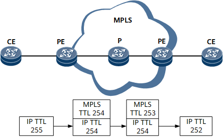
Uniform Mode
The IP TTL value reduces by one each time it passes through a node in an MPLS network.
When IP packets enter the MPLS network shown in Figure 4, the ingress reduces the IP TTL value by one and copies the IP TTL value to the MPLS TTL field. Each transit node only processes the MPLS TTL. Then the egress reduces the MPLS TTL value by one and copies the MPLS TTL value to the IP TTL field.
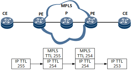
Pipe Mode
The IP TTL value decreases by one only when passing through the ingress and egress.
On the network shown in Figure 5, the ingress reduces the IP TTL value in packets by one and sets the MPLS TTL to a specific value. Transit nodes only process the MPLS TTL. When the egress receives the packets, it removes the MPLS label carrying the MPLS TTL from each packet and reduces the IP TTL value by one.