BGP 6PE
Background
As IPv6 technology becomes more popular, an increasing number of separate IPv6 networks take shape. IPv6 provider edge (6PE), a technology designed to provide IPv6 services over IPv4 networks, allows service providers to provide IPv6 services without constructing IPv6 backbone networks. The 6PE solution connects separate IPv6 networks using multiprotocol label switching (MPLS) tunnels. The 6PE solution implements IPv4/IPv6 dual stack on the provider edge devices (PEs) of Internet service providers and uses the Multi-protocol Extensions for Border Gateway Protocol (MP-BGP) to assign labels to IPv6 routes. In this manner, the 6PE solution connects separate IPv6 networks over IPv4 tunnels between PEs.
Related Concepts
Intra-AS 6PE: Separate IPv6 networks are connected by the same AS. PEs in the AS exchange IPv6 routes by establishing MP-IBGP peer relationships.
Inter-AS 6PE OptionB: ASBRs in different ASs exchange labeled IPv6 routes by establishing MP-EBGP peer relationships.
Inter-AS 6PE OptionB (with ASBRs as PEs): ASBRs in different ASs exchange IPv6 routes using MP-EBGP.
Inter-AS 6PE OptionC: PEs in different ASs exchange labeled IPv6 routes over multi-hop MP-EBGP peer sessions.
Intra-AS 6PE
Figure 1 shows intra-AS 6PE networking. 6PE runs on the edge of a service provider network. PEs that connect to IPv6 networks are IPv4/IPv6 dual-stack devices. PEs and customer edge devices (CEs) exchange IPv6 routes using the IPv6 Interior Gateway Protocol (IGP), or IPv6 External Border Gateway Protocol (EBGP). PEs exchange IPv4 routes with each other or with provider devices (Ps) using an IPv4 routing protocol. PEs must establish tunnels to transparently transmit IPv6 packets. PEs often use MPLS label switched paths (LSPs) and MPLS Local IFNET tunnels. By default, a PE uses an MPLS LSP to transmit IPv6 packets. If no MPLS LSP is available, a PE uses an MPLS Local IFNET tunnel to transmit IPv6 packets.
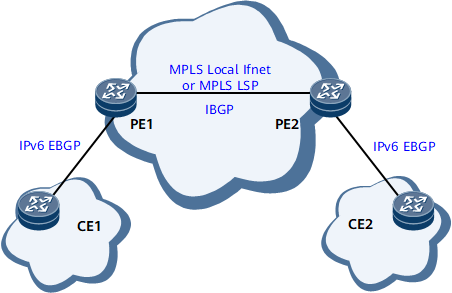
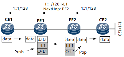
Figure 2 shows route and packet transmission in an intra-AS 6PE scenario. I-L indicates an inner label, and O-L indicates an outer label. The outer label directs the packet to the BGP next hop, and the inner label identifies the outbound interface or CE to which the packet should be forwarded.
- CE2 sends an IPv6 route to PE2, its EBGP peer.
- Upon receipt, PE2 changes the next hop of the IPv6 route to itself and assigns a label to the IPv6 route. Then, PE2 sends the labeled IPv6 route to PE1, its IBGP peer.
- Upon receipt, PE1 relays the labeled IPv6 route to a tunnel and adds information about the route to the local forwarding table. Then, PE1 changes the next hop of the route to itself, removes the label of the route, and sends the route to CE1, its EBGP peer.
- CE1 sends an ordinary IPv6 packet to PE1 over an IPv6 link on the public network.
- Upon receipt, PE1 searches its local forwarding table for the forwarding entry based on the destination address of the packet and encapsulates the packet with inner and outer labels. Then, PE1 sends the IPv6 packet to PE2 over a public network tunnel.
- Upon receipt, PE2 removes the inner and outer labels and forwards the IPv6 packet to CE2 over an IPv6 link.
The route and packet transmission processes show that whether the public network is an IPv4 or IPv6 network does not matter to the CEs.
Inter-AS 6PE
Inter-AS 6PE OptionB (with ASBRs as PEs)
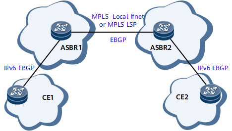
Figure 3 shows inter-AS 6PE OptionB (with ASBRs as PEs) networking. Inter-AS 6PE OptionB (with ASBRs as PEs) is similar to intra-AS 6PE. The only difference is that in an inter-AS 6PE OptionB scenario in which ASBRs also function as PEs, ASBRs establish EBGP peer relationships between each other. The route and packet transmission processes in an inter-AS 6PE OptionB scenario in which ASBRs also function as PEs are similar to those in an intra-AS 6PE scenario.
Inter-AS 6PE OptionB
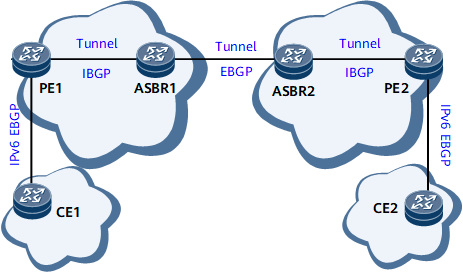
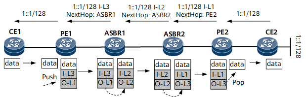
Figure 4 shows inter-AS 6PE OptionB networking. ASBRs exchange labeled IPv6 routes with each other or with PEs using an IPv4 routing protocol. Tunnels must be established between ASBRs and between PEs and ASBRs to transparently transmit IPv6 packets. MPLS LSPs, MPLS Local IFNET tunnels, GRE tunnels, and MPLS TE tunnels are often used between ASBRs to transmit IPv6 packets. By default, an ASBR uses an MPLS LSP to transmit IPv6 packets. If no MPLS LSP is available, an ASBR uses an MPLS Local IFNET tunnel to transmit IPv6 packets. If you want an ASBR to transmit IPv6 packets over an MPLS TE or a Generic Routing Encapsulation (GRE) tunnel, configure a tunnel policy on the ASBR.
Figure 5 shows route and packet transmission in an inter-AS 6PE OptionB scenario. I-L indicates an inner label, and O-L indicates an outer label.
The route transmission process is as follows:- CE2 sends an IPv6 route to PE2, its EBGP peer.
- Upon receipt, PE2 changes the next hop of the IPv6 route to itself and assigns a label to the IPv6 route. Then, PE2 sends the labeled IPv6 route to ASBR2 over an IBGP peer session.
- Upon receipt, ASBR2 relays the route to a tunnel and adds information about the route to the local forwarding table. Then, ASBR2 changes the next hop of the route to itself, replaces the label of the route, and sends the route to ASBR1, its EBGP peer.
- Upon receipt, ASBR1 relays the route to a tunnel and adds information about the route to the local forwarding table. Then, ASBR1 changes the next hop of the route to itself, replaces the label of the route, and sends the route to PE1, its IBGP peer.
- Upon receipt, PE1 relays the route to a tunnel and adds information about the route to the local forwarding table. Then, PE1 changes the next hop of the route to itself, removes the label of the route, and sends the route to CE1, its EBGP peer.
The packet transmission process is as follows:- CE1 sends an ordinary IPv6 packet to PE1 over an IPv6 link on the public network.
- Upon receipt, PE1 looks up its local forwarding table based on the destination address of the packet and encapsulates the packet with inner and outer labels. Then, PE1 sends the IPv6 packet to ASBR1 over a public network tunnel.
- Upon receipt, ASBR1 removes the inner and outer labels of the packet, looks up the local forwarding table based on the destination address of the packet, and encapsulates the packet with new inner and outer labels. Then, ASBR1 sends the IPv6 packet to ASBR2 over a public network tunnel.
- Upon receipt, ASBR2 removes the inner and outer labels of the packet, looks up the local forwarding table based on the destination address of the packet, and encapsulates the packet with new inner and outer labels. Then, ASBR2 sends the IPv6 packet to PE2 over a public network LSP.
- Upon receipt, PE2 removes the inner and outer labels and forwards the IPv6 packet to CE2 over an IPv6 link.
Inter-AS 6PE OptionC
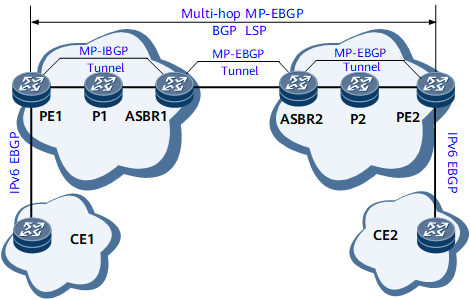
Figure 6 shows inter-AS 6PE OptionC networking. In an inter-AS 6PE OptionC scenario, PEs establish multi-hop MP-EBGP peer relationships between each other and exchange labeled IPv6 routes using an IPv4 routing protocol. PEs exchange IPv6 packets over end-to-end BGP LSPs.
Two inter-AS 6PE OptionC solutions are available, depending on the establishment methods of end-to-end LSPs. In an inter-AS 6PE OptionC scenario, PEs establish multi-hop MP-EBGP peer relationships to exchange labeled IPv6 routes and establish end-to-end BGP LSPs to transmit IPv6 packets. The way in which an end-to-end BGP LSP is established does not matter much to inter-AS 6PE OptionC and therefore is not described here.
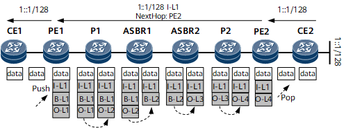
Figure 7 shows route and packet transmission in an inter-AS 6PE OptionC scenario. I-L indicates an inner label, B-L indicates a BGP LSP label, and O-L indicates an outer label. To simplify the description of the figure, it is assumed that:- The two ASBRs are connected by an MPLS Local IFNET tunnel.
- MPLS does not use the penultimate hop popping (PHP) function.
The route transmission process is as follows:- CE2 sends an IPv6 route to PE2, its EBGP peer.
- Upon receipt, PE2 changes the next hop of the IPv6 route to itself and assigns a label to the IPv6 route. Then, PE2 sends the labeled IPv6 route to PE1, its MP-EBGP peer.
- Upon receipt, PE1 relays the route to a tunnel and adds information about the route to the local forwarding table. Then, PE1 changes the next hop of the route to itself, removes the label of the route, and sends the route to CE1, its EBGP peer.
The packet transmission process is as follows:- CE1 sends an ordinary IPv6 packet to PE1 over an IPv6 link on the public network.
- Upon receipt, PE1 searches its local forwarding table for the forwarding entry based on the destination address of the packet, changes the next hop of the packet based on the search result, and encapsulates the packet with an inner label, a BGP LSP label, and an outer label. Then, PE1 sends the IPv6 packet to P1 over a public network tunnel.
- Upon receipt, P1 replaces the outer label of the packet and forwards the packet to ASBR1 over a public network tunnel.
- Upon receipt, ASBR1 removes the outer and BGP LSP labels and encapsulates the packet with a new BGP LSP label. Then, ASBR1 sends the IPv6 packet to ASBR2 over a public network tunnel.
- Upon receipt, ASBR2 removes the BGP LSP label and encapsulates the packet with an outer label. Then, ASBR2 sends the IPv6 packet to PE2 over a public network tunnel.
- Upon receipt, P2 replaces the outer label of the packet and forwards the packet to PE2 over a public network tunnel.
- Upon receipt, PE2 removes the inner and outer labels and forwards the IPv6 packet to CE2 over an IPv6 link.
Usage Scenarios
Each 6PE mode has its advantages and usage scenarios. The intra-AS 6PE mode is best suited for scenarios in which separate IPv6 networks connect to the same AS. Inter-AS 6PE modes are best suited for scenarios in which separate IPv6 networks connect to different ASs. Table 1 lists the usage scenarios for inter-AS 6PE modes.
Mode |
Characteristic |
Usage Scenario |
|---|---|---|
Inter-AS 6PE OptionB (with ASBRs as PEs) |
Advantage: Configuration is similar to that for intra-AS 6PE and additional inter-AS configuration is not required. Disadvantage: Network expansibility is poor. ASBRs must have high performance to manage information about all labeled IPv6 routes. |
A small network with ASBRs in different ASs to which separate IPv6 networks are connected. The smaller the number of ASs spanned, the more obvious the advantage of this solution is. |
Inter-AS 6PE OptionB |
Advantage: MPLS tunnels are established segment by segment and easy to manage. Disadvantage: Information about labeled IPv6 routes is stored on and advertised by ASBRs. If a large number of VPN routes exist, the overburdened ASBRs are likely to encounter bottlenecks. |
An inter-AS OptionB public network with tunnels established between the PEs in different ASs and with separate IPv6 networks connected to the ASs. |
Inter-AS 6PE OptionC |
Advantage: Labeled IPv6 routes are directly exchanged between the ingress and egress PEs. Information about labeled IPv6 routes is managed by PEs only and ASBRs are no longer the bottlenecks. Disadvantage: Management costs of end-to-end BGP LSP connections are high. |
An inter-AS OptionC public network with end-to-end tunnels established between the PEs in different ASs and with separate IPv6 networks connected to the ASs. The greater the number of ASs spanned, the more obvious the advantage of this solution is. |
Benefits
6PE offers the following benefits:
Easy maintenance: All configurations are performed on PEs and network maintenance is simple. IPv6 services are carried over IPv4 networks, but the users on IPv6 networks are unaware of IPv4 networks.
Low network construction costs: Service providers can provide IPv6 services over existing MPLS networks without upgrading the networks. 6PE devices can provide multiple types of services, such as IPv6 VPN and IPv4 VPN.