Overview of VLANs
Definition
The virtual local area network (VLAN) technology logically divides a physical LAN into multiple VLANs that are broadcast domains. Each VLAN contains a group of PCs that have the same requirements. A VLAN has the same attributes as a LAN. PCs of a VLAN can be placed on different LAN segments. Hosts can communicate within the same VLAN, while cannot communicate in different VLANs. If two PCs are located on one LAN segment but belong to different VLANs, they do not broadcast packets to each other. In this manner, network security is enhanced.
Purpose
The network constructs a collision domain. More computers on the network cause more conflicts and lower network efficiency. The network is also a broadcast domain. When many computers on the network send data, broadcast traffic consumes much bandwidth.
Traditional networks face collision domain and broadcast domain issues, and cannot ensure information security.
To offset the defects, bridges and Layer 2 switches are introduced to consummate the traditional LAN.
Bridges and Layer 2 switches can forward data from the inbound interface to outbound interface in switching mode. This properly solves the access conflict problem on the shared media, and limits the collision domain to the port level. Nevertheless, the bridge or Layer 2 switch networking can only solve the problem of the collision domain, but not the problems of broadcast domain and network security.

In this document, the Layer 2 switch is referred to as the switch for short.
To reduce the broadcast traffic, you need to enable the broadcast only among hosts that need to communicate with each other, and isolate the hosts that do not need the broadcast. A router can select routes based on IP addresses and effectively suppress broadcast traffic between two connected network segments. The router solution, however, is costly. Therefore, multiple logical LANs, namely, VLANs are developed on the physical LAN.
In this manner, a physical LAN is divided into multiple broadcast domains, that is, multiple VLANs. The intra-VLAN communication is not restricted, while the inter-VLAN communication is restricted. As a result, network security is enhanced.
For example, if different companies in the same building build their LANs separately, it is costly; if these companies share the same LAN in the building, there may be security problems.
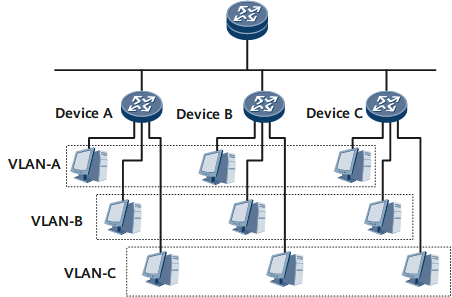
Figure 1 is a networking diagram of a typical VLAN application. Device A, Device B, and Device C are placed at different locations, such as different floors in an office building. Each switch connects to three computers which belong to three different VLANs. In Figure 1, each dashed line frame identifies a VLAN. Packets of enterprise customers in the same VLAN are broadcast within the VLAN but not among VLANs. In this way, enterprise customers in the same VLAN can share resources as well as protect their information security.
- Broadcast domains are confined. A broadcast domain is confined to a VLAN. This saves bandwidth and improves network processing capabilities.
- Network security is enhanced. Packets from different VLANs are separately transmitted. PCs in one VLAN cannot directly communicate with PCs in another VLAN.
- Network robustness is improved. A fault in a VLAN does not affect PCs in other VLANs.
- Virtual groups are set up flexibly. With the VLAN technology, PCs in different geographical areas can be grouped together. This facilitates network construction and maintenance.
Benefits
Saves network bandwidth resources by isolating broadcast domains.
Improves communication security and facilitates service deployment.