IS-IS MT
With IS-IS multi-topology (MT), IPv6, multicast, and advanced topologies can have their own routing tables. This feature prevents packet loss if an integrated topology and the IPv4/IPv6 dual stack are deployed, isolates multicast services from unicast routes, improves network resource usage, and reduces network construction cost.
Introduction
- Packet loss if the IPv4/IPv6 dual stack is deployed: If some routers and links in an IPv4/IPv6 topology do not support IPv4 or IPv6, they cannot receive IPv4 or IPv6 packets sent from the router that supports the IPv4/IPv6 dual stack. As a result, these packets are discarded.
- Multicast services highly depending on unicast routes: Only one unicast forwarding table is available on the forwarding plane because only one unicast topology exists, which forces services transmitted from one router to the same destination address to share the same next hop, and various end-to-end services, such as voice and data services, to share the same physical links. As a result, some links may be heavily congested whereas others remain relatively idle. In addition, the multicast reverse path forwarding (RPF) check depends on the unicast routing table. If the default unicast routing table is used when transmitting multicast services, multicast services depend heavily on unicast routes, a multicast distribution tree cannot be planned independently of unicast routes, and unicast route changes affect multicast distribution tree establishment.
Deploying multiple topologies for different services on a physical network can address these problems. IS-IS MT transmits multi-topology information by defining new TLVs in IS-IS packets. Users can deploy multiple logical topologies on a physical network based on IP protocols or service types supported by links so that separate SPF calculation operations are performed in different topologies, which improves network usage.

If an IPv4 or IPv6 BFD session is Down in a topology on a network enabled with MT, neighbors of the IPv4 or IPv6 address family will be affected.
Related Concepts
IS-IS MT allows multiple route selection subsets to be deployed on a versatile network infrastructure and divides a physical network into multiple logical topologies, where each topology performs its own SPF calculations.
IS-IS MT, an extension of IS-IS, allows multiple topologies to be applied to IS-IS. IS-IS MT complies with standard protocols and transmits multi-topology information using new TLVs in IS-IS packets. Users can deploy multiple logical topologies on a physical network. Each topology performs its own SPF calculations and maintains its own routing table. Traffic of different services, including the traffic transmitted in different IP topologies, has its own optimal forwarding path.
The MT ID configured on an interface identifies the topology bound to the interface. One or more MT IDs can be configured on a single interface.
With RPF check, upon receiving a packet, a router searches multicast static, unicast, Multiprotocol Border Gateway Protocol (MBGP), and Multicast Interior Gateway Protocol (MIGP) routing tables for an optimal route and sets it as the RPF route to the source IP address of the packet. The packet can be transmitted only when it is destined for the RPF interface.
Implementation
In IS-IS MT, the MT ID varies with the topology. Each Hello packet or LSP sent by a router carries one or more MT TLVs of the topologies to which the source interface belongs. If the router receives from a neighbor a Hello packet or LSP that carries only some of the local MT TLVs, the router assumes that the neighbor belongs to only the default IPv4 topology. On a point-to-point (P2P) link, an adjacency cannot be established between two neighbors that share no common MT ID, while on a broadcast link, the relationship can be established in this case.
Figure 1 shows the MT TLV format.
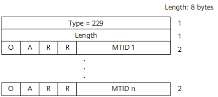
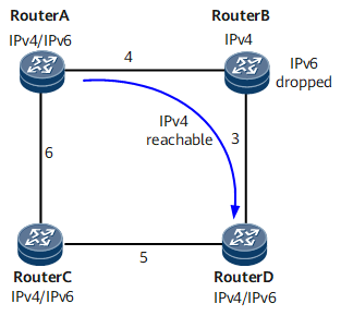
Figure 2 shows the networking for separation of the IPv4 topology from the IPv6 topology. The values in the networking diagram are link costs. Device A, Device C, and Device D support the IPv4/IPv6 dual stack; Device B supports IPv4 only and cannot forward IPv6 packets.
Without IS-IS MT, Device A, Device B, Device C, and Device D use the IPv4/IPv6 topology for the SPF calculation. In this case, the shortest path from Device A to Device D is Device A -> Device B- > Device D. IPv6 packets cannot reach Device D through Device B because Device B does not support IPv6.
If a separate IPv6 topology is set up using IS-IS MT, Device A chooses only IPv6 links to forward IPv6 packets. In this case, the shortest path from Device A to Device D is Device A -> Device C -> Device D.
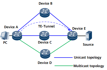
Figure 3 shows the networking for separation between unicast and a multicast topologies using IS-IS MT.
On the network shown in Figure 3, all routers are interconnected using IS-IS. A TE tunnel is set up between Device A (ingress) and Device E (egress). The outbound interface of the route calculated by IS-IS may not be a physical interface but a TE tunnel interface. In this case, router C through which the TE tunnel passes cannot set up multicast forwarding entries. As a result, multicast services cannot be transmitted.
IS-IS MT addresses this problem by establishing separate unicast and multicast topologies. TE tunnels are excluded from a multicast topology. Therefore, multicast services are unaffected by TE tunnels.