Multicast Multi-Topology
Multi-topology is a method that divides a physical network into multiple logical topologies. Multicast multi-topology is a typical application of multi-topology.
Without multicast multi-topology, multicast routing heavily depends on unicast routing. Therefore, unicast route changes affect the setup of an MDT.
Multicast multi-topology resolves this problem by enabling the system to generate a multicast multi-topology routing table dedicated to multicast services so that multicast routing no longer completely depends on unicast routing tables.
When a multicast router performs a reverse path forwarding (RPF) check, the router searches for routes and builds a multicast forwarding tree only in the multicast topology.
Figure 1 shows an implementation of multicast multi-topology.
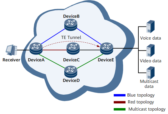
Use multicast multi-topology to deploy multicast services on a network that has a unidirectional Multiprotocol Label Switching – Traffic Engineering (MPLS TE) tunnel configured.
On the network, a unidirectional MPLS TE tunnel is established, and multicast services are enabled. After Interior Gateway Protocol (IGP) Shortcut or Forwarding Advertise (FA) is configured, the outbound interface of the route calculated by IGP is not the actual physical interface but a TE tunnel interface. A receiver joins a multicast group, but the multicast data sent by the server can only travel through Device E and reach Device C through a physical link. This is because the TE tunnel is unidirectional. Device C has no multicast routing entries, so it does not forward the multicast data to the receiver. The multicast service fails to work for this receiver.
Multicast multi-topology resolves this problem by dividing the network into several logical topologies. For example, the links in green shown in Figure 1 construct a multicast topology and the network operators deploy multicast services only in the multicast topology. Then, after Device A receives a Join message from the receiver and performs the RPF check, it selects only the route in the multicast topology with the upstream device being Device D and sets up an MDT hop-by-hop. The multicast data travels through the path Device E → Device D → Device A and successfully reaches the receiver.

Do not configure a unidirectional MPLS TE tunnel in a multicast topology.
Use multicast multi-topology to isolate multicast services from unicast services.
If multiple types of services are deployed on a network, these services share the physical topology. For example, the links Device E→Device B→Device A and Device E→Device C→Device A may run mission-critical unicast services that keep the links very busy. Network operators can set up another link Device E→Device D→Device A to carry only multicast services and isolate multicast services from unicast services.
After a receiver sends a Join message to a multicast router, the multicast router performs an RPF check based on the unicast route in the multicast topology and establishes an MDT hop by hop. The multicast data then travels through the path Device E → Device D → Device A and reaches the receiver.