Basic Concepts
Interface Types
Devices exchange data and interact with other devices on a network through interfaces. Interfaces are classified into physical and logical interfaces.
-
Physical interfaces physically exist on boards. They are divided into the following types:
- LAN interfaces: interfaces through which the router can exchange data with other devices on a LAN.
- WAN interfaces: interfaces through which the router can exchange data with remote devices on external networks.
-
Logical interfaces are manually configured interfaces that do not exist physically. Logical interfaces can be used to exchange data.
Interface Views and Prompts
Table 1 lists the commands, views, and prompts of physical interfaces supported by the NetEngine 8000 F. Table 2 lists the commands, views, and prompts of logical interfaces supported by the NetEngine 8000 F.
Interface Name |
Command View |
Operation |
Prompt |
|---|---|---|---|
GE interface |
GE interface view |
Run the interface gigabitethernet 0/1/0 command in the system view. |
[~HUAWEI-GigabitEthernet0/1/0] |
10GE interface |
10GE interface view |
Run the interface gigabitethernet 0/1/0 command in the system view. NOTE:
The interfaces marked with 10G displayed in the display interface brief command output indicate GE interfaces whose bandwidth is 10 Gbit/s. |
[~HUAWEI-GigabitEthernet0/1/0] |
25GE interface view |
25GE interface view |
Run the interface 25GE 0/1/0 command in the system view. Run the interface 25GE 0/1/28 command in the system view. |
[~HUAWEI-25GE0/1/0] [~HUAWEI-25GE0/1/28] |
40GE interface |
40GE interface view |
Run the interface 40GE 0/1/0 command in the system view. Run the interface 40GE 0/1/48 command in the system view. |
[~HUAWEI-40GE0/1/0] [~HUAWEI-40GE0/1/48] |
100GE interface |
100GE interface view |
Run the interface 100GE 0/1/0 command in the system view. Run the interface 100GE 0/1/48 command in the system view. |
[~HUAWEI-100GE0/1/0] [~HUAWEI-100GE0/1/48] |
400GE interface |
400GE interface view |
Run the interface 400GE 0/1/0 command in the system view. |
[~HUAWEI-400GE0/1/0] |
XGE interface |
XGE interface view |
Run the interface XGigabitEthernet 0/1/0 command in the system view. |
[~HUAWEI-XGigabitEthernet0/1/0] |
50GE interface |
50GE interface view |
Run the interface 50GE 0/1/0 command in the system view. Run the interface 50GE 0/1/48 command in the system view. |
[~HUAWEI-50GE0/1/0] [~HUAWEI-50GE0/1/48] |
FlexE-50G interface |
FlexE-50G interface view |
Run the interface FlexE-50G 0/1/0 command in the system view. Run the interface FlexE-50G 0/1/48 command in the system view. |
[~HUAWEI-FlexE-50G0/1/0] [~HUAWEI-FlexE-50G0/1/48] |
FlexE-100G interface |
FlexE-100G interface view |
Run the interface FlexE-100G 0/1/0 command in the system view. Run the interface FlexE-100G 0/1/48 command in the system view. |
[~HUAWEI-FlexE-100G0/1/0] [~HUAWEI-FlexE-100G0/1/48] |
FlexE-400G interface |
FlexE-400G interface view |
Run the interface FlexE-400G 0/1/0 command in the system view. |
[~HUAWEI-FlexE-400G0/1/0] |
Interface Name |
Command View |
Operation |
Prompt |
|---|---|---|---|
Sub-interface |
Sub-interface view |
Run the interface gigabitethernet 0/1/0.1 command in the system view. |
[~HUAWEI-GigabitEthernet0/1/0.1] |
Eth-Trunk interface |
Eth-Trunk interface view |
Run the interface eth-trunk 2 command in the system view. |
[~HUAWEI-Eth-Trunk2] |
VE interface |
VE interface view |
Run the interface virtual-ethernet 0/1/0 command in the system view. |
[~HUAWEI-Virtual-Ethernet0/1/0] |
Global-VE interface |
Global VE interface view |
Run the interface global-ve 0/1/0 command in the system view. |
[~HUAWEI-Global-VE0/1/0] |
VLANIF interface |
VLANIF interface view |
Run the interface vlanif 2 command in the system view. |
[~HUAWEI-Vlanif2] |
Loopback interface |
Loopback interface view |
Run the interface loopback 2 command in the system view. |
[~HUAWEI-LoopBack2] |
Null interface |
Null interface view |
Run the interface null 0 command in the system view. |
[~HUAWEI-NULL0] |
Tunnel interface |
Tunnel interface view |
Run the interface tunnel 2 command in the system view. |
[~HUAWEI-Tunnel 2] |
FlexE interface |
FlexE interface view |
Run the interface FlexE 0/1/129 command in the system view. |
[~HUAWEI-FlexE0/1/129] |
PW-VE interface |
PW-VE interface view |
Run the interface pw-ve 1 command in the system view. |
[~HUAWEI-pw-ve1] |
Commonly-used Link Protocols and Access Technologies
The link layer is responsible for accurately sending data from a node to a neighboring node. It receives packets from the network layer, encapsulates the packets in frames, and then sends the frames to the physical layer.
Major link layer protocols supported by the NetEngine 8000 F are listed as follows:
-
Currently, the LAN mostly refers to the Ethernet. The Ethernet is a broadcast network, which is flexible and simple in configuration as well as easy to expand. For these reasons, the Ethernet is widely used.
-
The trunk technology has the following advantages:
- Bandwidth increase: The bandwidth of a trunk is the total bandwidth of all member interfaces.
- Reliability enhancement: When a link fails, other links in the same trunk automatically take over the services on the faulty link to prevent traffic interruption.
MTU
The maximum transmission unit (MTU) is the size (in bytes) of the longest packet that can be transmitted on a physical network. The MTU is very important for interworking between two devices on a network. If the size of a packet exceeds the MTU supported by a transit node or a receiver, the transit node or receiver may fragment the packet before forwarding it or may even discard it, increasing the network transmission loads. MTU values must be correctly negotiated between devices to ensure that packets reach the receiver.
If fragmentation is disallowed, packet loss may occur during data transmission at the IP layer. To ensure that long packets are not discarded during transmission, configure forcible fragmentation for long packets.
When an interface with a small MTU receives long packets, the packets have to be fragmented. Consequently, when the quality of service (QoS) queue becomes full, some packets may be discarded.
If an interface has a large MTU, packets may be transmitted at a low speed.
Loopback
The physical interface of the router supports loopback local and loopback remote. The following figure shows the two loopback paths.
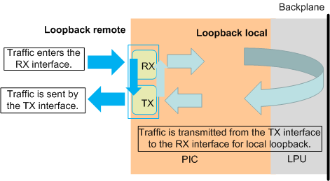
loopback local
The differences between local loopback and optical fiber loopback based on optical modules are as follows: In the local loopback mode, service traffic does not pass through the Framer's optical module driver circuit. During the forwarding tests, only a few boards inserted with optical modules perform optical fiber loopback to test the Framer's optical module driver circuit. Local loopback can be configured on the interfaces to test the forwarding performance and stability, which saves materials.
Redirection is a class behavior of a QoS policy. Redirection can change the IP packets' next-hop IP addresses and outbound interfaces, and apply to specific interfaces to change the IP service forwarding destination. When redirection works with interface loopback, you can use the interface connected to the tester to test all the interfaces on the board. If only loopback local is configured on the interface and redirection is not configured or the configured policy is not matched, the system does not forward packets.
Local loopback can also verify system functions. Take the mirroring function as an example. Due to limited materials, you can run the loopback local command on the observing interface to monitor the traffic and verify whether the function takes effect.
loopback remote
Remote loopback is used for fault diagnosis at the physical layer. You can check physical link quality through the subcard statistics, interface status, or other parameters.
Figure 2 Remote loopback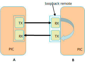
As shown in the preceding figure, after the interface with loopback remote configured receives a packet from A, B does not forward the packet based on the destination address. Instead, B directly returns the packet through another interface (Layer 2 or Layer 3 interface) to A.
The processing on A when A receives the returned packet from B is as follows:
- If the interface on A is a Layer 3 interface, Ping packets looped back from B is discarded by A because the destination MAC address is different from the MAC address of the interface on End A. However, interface statistics exist on the subcard. You can check physical link quality by the Input and Output fields on the interface.
If the interface on A is a Layer 2 interface, the interface cannot successfully transmit Ping packets. If a tester or other methods are used for A to transmit a packet, A does not check the MAC address of the packet looped back from B, and instead, A directly forwards the packet based on the MAC address.
- If A sends the packet with the MAC address of the peer device as the destination MAC address, the packet is repeatedly looped back between the two devices.
- If A sends the packet whose destination MAC address is a broadcast MAC address, the packet is repeatedly looped back between two devices and is broadcast to the broadcast domain.
This method causes broadcast storms. Therefore, exercise caution when using this method.
Control-Flap
The status of an interface on a device may alternate between up and down for various reasons, including physical signal interference and incorrect link layer configurations. The changing status causes Multiprotocol Label Switching (MPLS) and routing protocols to flap. As a result, the device may break down, causing network interruption. Control-flap controls the frequency of interface status alternations between up and down to minimize the impact on device and network stability.
The following two control modes are available.
Control Mode |
Function |
Usage Scenario |
|---|---|---|
control-flap |
Controls the frequent flappings of interfaces at the network layer to minimize the impact on device and network stability. |
|
damp-interface |
Controls the frequent flappings of interfaces at the physical layer to minimize the impact on device and network stability. |
|
control-flap
Interface flapping control controls the frequency of interface status alternations between Up and Down to minimize the impact on device and network stability.
Interface flapping suppression involves the following concepts:
Penalty value and threshold
An interface is suppressed or freed from suppression based on the penalty value.
- Penalty value: This value is calculated based on the status of the interface using the suppression algorithm. The penalty value increases with the changing times of the interface status and decreases with the half life.
- Suppression threshold (suppress): The interface is suppressed when the penalty value is greater than the suppression threshold.
- Reuse threshold (reuse): The interface is no longer suppressed when the penalty value is smaller than the reuse threshold.
- Ceiling threshold (ceiling): The penalty value no longer increases when the penalty value reaches the ceiling threshold.
The parameter configuration complies with the following rule: reuse threshold (reuse) < suppression threshold (suppress) < maximum penalty value (ceiling).
Half life
When an interface goes down for the first time, the half life starts. A device matches against the half life based on the actual interface status. If a specific half life is reached, the penalty value decreases by half. Once a half life ends, another half life starts.
- Half life when an interface is up (decay-ok): When the interface is up, if the period since the end of the previous half life reaches the current half life, the penalty value decreases by half.
- Half life when an interface is down (decay-ng): When the interface is down, if the period since the end of the previous half life reaches the current half life, the penalty value decreases by half.
- Maximum suppression time: The maximum suppression time of an interface is 30 minutes. When the period during which an interface is suppressed reaches the maximum suppression time, the interface is automatically freed from suppression.
- You can set the preceding parameters to restrict the frequency at which an interface alternates between up and down.
Comply with the following rules when configuring parameters.
Table 4 Flapping control parameter configuration recommendations Configuration Objective
Recommendations
suppress
reuse
decay-ok
decay-ng
To delay interface suppression
Increase
N/A
Decrease
Decrease
To accelerate interface suppression
Decrease
N/A
Increase
Increase
To accelerate disabling interface suppression
N/A
Increase
Decrease
Decrease
To delay disabling interface suppression
N/A
Decrease
Increase
Increase
decay-ok and decay-ng can be configured separately:
If an interface remains up for a long period and the interface needs to be used as soon as it goes up, decreasing decay-ok is recommended.
If an interface remains down for a long period and the interface needs to be suppressed as soon as it goes down, increasing decay-ng is recommended.
Example:
Table 5 Example for setting the control-flap parameter Parameter
Examples for the Impact of Flapping Control Parameters on Interface Suppression
suppress

reuse

decay-ok and decay-ng

Principles of interface flapping control:
In Figure 3, the default penalty value of an interface is 0. The penalty value increases by 400 each time the interface goes down. When an interface goes down for the first time, the half life starts. The system checks whether the specific half life expires at an interval of 1s. If the specific half life expires, the penalty value decreases by half. Once a half life ends, another half life starts.
If the penalty value exceeds the interface suppressing threshold, the interface is suppressed. When the interface is suppressed, the outputs of the display interface, display interface brief, and display ip interface brief commands show that the protocol status of the interface remains DOWN(dampening suppressed) and does not change with the physical status.
If the penalty value falls below the interface reuse threshold, the interface is freed from suppression. When the interface is freed from suppression, the protocol status of the interface is in compliance with the actual status and does not remain Down (dampening suppressed).
If the penalty value reaches ceiling, the penalty value no longer increases.
damp-interface
Related concepts:
- penalty value: a value calculated by a suppression algorithm based on an interface's flappings. The suppression algorithm increases the penalty value by a specific value each time an interface goes down and decreases the penalty value exponentially each time the interface goes up.
- suppress: An interface is suppressed if the interface's penalty value is greater than the suppress value.
- reuse: An interface is no longer suppressed if the interface's penalty value is less than the reuse value.
- ceiling: calculated using the formula of reuse x 2 (MaxSuppressTime/HalfLifeTime). ceiling is the maximum penalty value. An interface's penalty value no longer increases when it reaches ceiling.
- half-life-period: period that the penalty value takes to decrease to half. A half-life-period begins to elapse when an interface goes Down for the first time. If a half-life-period elapses, the penalty value decreases to half, and another half-life-period begins.
- max-suppress-time: maximum period during which an interface's status is suppressed. After max-suppress-time elapses, the interface's actual status is reported to upper layer services.
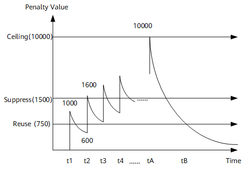
Figure 4 shows the relationship between the preceding parameters. To facilitate understanding, figures in Figure 4 are all multiplied by 1000.
At t1, an interface goes down, and its penalty value increases by 1000 (The actual penalty value on the device is 1. The penalty values in this example are 1000 times the actual penalty values). Then, the interface goes up, and its penalty value decreases exponentially based on the half-life rule. At t2, the interface goes down again, and its penalty value increases by 1000, reaching 1600, which has exceeded the suppress value 1500. At this time if the interface goes up again, its status is suppressed. As the interface keeps flapping, its penalty value keeps increasing until it reaches the ceiling value 10000 at tA. As time goes by, the penalty value decreases and reaches the reuse value 750 at tB. The interface status is then no longer suppressed.


Loopback interfaces, Layer 2 interfaces that are converted from Layer 3 interfaces using the portswitch command, and Null interfaces do not support MTU or control-flap configuration.