OSPF Fundamentals
OSPF route calculation involves the following processes:
-
The adjacency establishment process is as follows:
- The local and remote devices use OSPF interfaces to exchange Hello packets to establish a Neighbor relationship.
- The local and remote devices negotiate a master/slave relationship and exchange Database Description (DD) packets.
- The local and remote devices exchange link state advertisements (LSAs) to synchronize their link state databases (LSDBs).
Route calculation: OSPF uses the shortest path first (SPF) algorithm to calculate routes, implementing fast route convergence.
OSPF Neighbor States
To exchange routing information on an OSPF network, neighbor devices must establish adjacencies. The differences between neighbor relationships and adjacencies are described as follows:
- Neighbor relationship: After the local device starts, it uses an OSPF interface to send a Hello packet to the remote device. After the remote device receives the packet, it checks whether the parameters carried in the packet are consistent with its own parameters. If the parameters carried in the packet are consistent with its own parameters, the remote device establishes a neighbor relationship with the local device.
- Adjacency: After the local and remote devices establish a neighbor relationship, they exchange DD packets and LSAs to establish an adjacency.
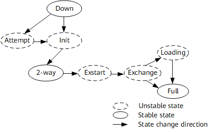
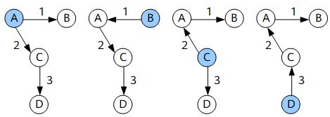
OSPF has eight neighbor states: Down, Attempt, Init, 2-way, Exstart, Exchange, Loading, and Full, as shown in Figure 1. Down, 2-way, and Full are stable states. Attempt, Init, Exstart, Exchange, and Loading are unstable states, which last only several minutes.
OSPF Neighbor State |
Meaning |
|---|---|
Down |
This is the initial state of a neighbor conversation. This state indicates that a device has not received any Hello packets from its neighbors within a dead interval. |
Attempt |
In the Attempt state, a device periodically sends Hello packets to manually configured neighbors. NOTE:
The Attempt state applies only to non-broadcast multiple access (NBMA) interfaces. |
Init |
This state indicates that a device has received Hello packets from its neighbors but the neighbors did not receive Hello packets from the device. |
2-way |
This state indicates that a device has received Hello packets from its neighbors and a neighbor relationship has been established between the devices. If no adjacency needs to be established, the neighbors remain in the 2-way state. If adjacencies need to be established, the neighbors enter the Exstart state. |
Exstart |
In this state, devices establish a master/slave relationship to ensure that DD packets are sequentially exchanged. |
Exchange |
In the Exchange state, devices exchange DD packets. A device uses a DD packet to describe its own LSDB and sends the packet to its neighbors. |
Loading |
In this state, a device sends Link State Request (LSR) packets to its neighbors to request their LSAs for LSDB synchronization. |
Full |
In this state, the local device have established adjacencies with its neighbors and their LSDBs have been synchronized. |

The neighbor state of the local device may be different from that of a remote device. For example, the neighbor state of the local device is Full, but the neighbor state of the remote device is Loading.
Adjacency Establishment
Adjacencies can be established in either of the following situations:
Two devices have established a neighbor relationship and communicate for the first time.
The designated router (DR) or backup designated router (BDR) on a network segment changes.
The adjacency establishment process is different on different networks.
Adjacency establishment on a broadcast network
On a broadcast network, the DR and BDR establish adjacencies with each device on the same network segment, but DR others establish only neighbor relationships.
On a broadcast network, the DR and BDR establish adjacencies with each router on the network segment, but DR others establish only neighbor relationships.
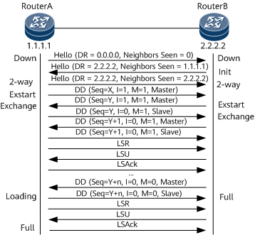
Figure 2 shows the process of OSPF adjacency establishment on a broadcast network.
Neighbor relationship establishment
RouterA sends a Hello packet using the multicast address 224.0.0.5 through the OSPF interface connected to a broadcast network. RouterA does not know which router is the DR or which router is a neighbor. Therefore, the DR field carried in the packet is 0.0.0.0, and the Neighbors Seen field is 0.
After Router B receives the packet, it returns a Hello packet to Router A. The returned packet carries the DR field of 2.2.2.2 (ID of Router B) and the Neighbors Seen field of 1.1.1.1 (Router A's router ID). Router A has been discovered but its router ID is less than that of Router B, and therefore Router B regards itself as a DR. Then Router B's state changes to Init.
After Router A receives the packet, Router A's state changes to 2-way.
The following procedures are not performed for routers that function as DR others on a broadcast network.
Master/Slave negotiation and DD packet exchange
- Router A sends a DD packet to Router B. The packet carries the following fields:
- Seq field: The value x indicates the sequence number is x.
- I field: The value 1 indicates that the packet is the first DD packet, which is used to negotiate a master/slave relationship and does not carry LSA summaries.
- M field: The value 1 indicates that the packet is not the last DD packet.
- MS field: The value 1 indicates that Router A declares itself a master.
To improve transmission efficiency, Router A and Router B determine which LSAs in each other's LSDB need to be updated. If one party determines that an LSA of the other party is already in its own LSDB, it does not send an LSR packet for updating the LSA to the other party. To achieve the preceding purpose, Router A and Router B first send DD packets, which carry summaries of LSAs in their own LSDBs. Each summary identifies an LSA. To ensure packet transmission reliability, a master/slave relationship must be determined during DD packet exchange. One party serving as a master uses the Seq field to define a sequence number. The master increases the sequence number by one each time it sends a DD packet. When the other party serving as a slave sends a DD packet, it adds the sequence number carried in the last DD packet received from the master to the Seq field of the packet.
After Router B receives the DD packet, Router B's state changes to Exstart and Router B returns a DD packet to Router A. The returned packet does not carry LSA summaries. Because Router B's router ID is greater than Router A's router ID, Router B declares itself a master and sets the Seq field to y.
After Router A receives the DD packet, it agrees that Router B is a master and Router A's state changes to Exchange. Then Router A sends a DD packet to Router B to transmit LSA summaries. The packet carries the Seq field of y and the MS field of 0. The value 0 indicates that Router A declares itself a slave.
After Router B receives the packet, Router B's state changes to Exchange and Router B sends a new DD packet containing its own LSA summaries to Router A. The value of the Seq field carried in the new DD packet is changed to y + 1.
Router A uses the same sequence number as Router B to confirm that it has received DD packets from Router B. Router B uses the sequence number plus one to confirm that it has received DD packets from Router A. When Router B sends the last DD packet, it sets the M field of the packet to 0.
LSDB synchronization (LSA request, LSA transmission, and LSA response)
After Router A receives the last DD packet, it finds that many LSAs in Router B's LSDB do not exist in its own LSDB, so Router A's state changes to Loading. After Router B receives the last DD packet from Router A, Router B's state directly changes to Full, because Router B's LSDB already contains all LSAs of Router A.
RouterA sends an LSR packet for updating LSAs to RouterB. RouterB returns an LSU packet to RouterA. After RouterA receives the packet, it sends an LSAck packet for acknowledgment.
The preceding procedures continue until the LSAs in RouterA's LSDB are the same as those in RouterB's LSDB. RouterA's state changes to Full. After routers exchange DD packets and update all LSAs, they establish an adjacency.
OSPF adjacency establishment on an NBMA network
The adjacency establishment process on an NBMA network is similar to that on a broadcast network. The blue part shown in Figure 3 highlights the differences from a broadcast network.
On an NBMA network, all routers establish adjacencies only with the DR and BDR.
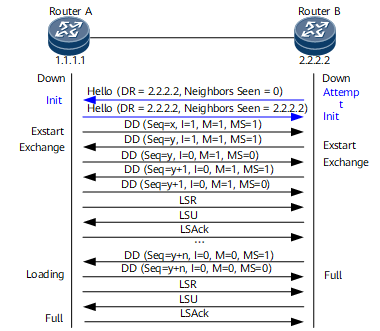
Figure 3 shows the process of OSPF adjacency establishment on an NBMA network.
Neighbor relationship establishment
After RouterB sends a Hello packet to a down interface of RouterA, RouterB's state changes to Attempt. The packet carries the DR field of 2.2.2.2 (ID of Router B) and the Neighbors Seen field of 0. A neighbor router has not been discovered, and Router B regards itself as a DR.
After RouterA receives the packet, RouterA's state changes to Init and RouterA returns a Hello packet. The returned packet carries the DR and Neighbors Seen fields of 2.2.2.2. RouterB has been discovered but its router ID is greater than that of RouterA, and therefore Router A agrees that Router B is a DR.
The following procedures are not performed for DR others on an NBMA network.
Master/Slave relationship negotiation and DD packet exchange
The procedures for negotiating a master/slave relationship and exchanging DD packets on an NBMA network are the same as those on a broadcast network.
LSDB synchronization
The procedure for synchronizing LSDBs on an NBMA network is the same as that on a broadcast network.
Adjacency establishment on a point-to-point (P2P)/Point-to-multipoint (P2MP) network
The adjacency establishment process on a P2P/P2MP network is similar to that on a broadcast network. On a P2P/P2MP network, however, no DR or BDR needs to be elected and DD packets are transmitted in multicast mode.
Route Calculation
OSPF uses the shortest path first (SPF) algorithm to calculate routes, implementing fast route convergence.
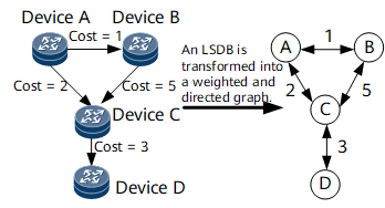
OSPF uses an LSA to describe the network topology. A Router LSA describes the attributes of a link between routers. A router transforms its LSDB into a weighted, directed graph, which reflects the topology of the entire network. All routers in the same area have the same graph. Figure 4 shows a weighted, directed graph.
Based on the graph, each router uses the SPF algorithm to calculate an SPT with itself as the root. The SPT shows routes to nodes in the AS. Figure 5 shows an SPT.
When a router's LSDB changes, the router recalculates a shortest path. Frequent SPF calculations consume a large amount of resources and affect router efficiency. Changing the interval between SPF calculations can prevent resource consumption caused by frequent LSDB changes. The default interval between SPF calculations is 5 seconds.
The route calculation process is as follows:
A device calculates intra-area routes.
The router uses an SPF algorithm to calculate shortest paths to other routers in an area. Router LSAs and Network LSAs accurately describe the network topology in an area. Based on the Router LSAs and the network segments of the router, paths to the network segments are calculated.
If multiple equal-cost routes are produced during route calculation, the SPF algorithm retains all these routes in the LSDB.
The device calculates inter-area routes.
For the devices in an area, the network segment of the routes in an adjacent area is directly connected to the area border router (ABR). Because the shortest path to the ABR has been calculated in the preceding step, the devices can directly check a Network Summary LSA to obtain the shortest path to the network segment. The autonomous system boundary router (ASBR) can also be considered connected to the ABR. Therefore, the shortest path to the ASBR can also be calculated in this phase.
If the router performing an SPF calculation is an ABR, it needs to check only Network Summary LSAs in the backbone area.
If there are multiple paths to the ASBR, check whether the route selection rules of intra- and inter-type ASBRs on different types of devices are the same. If the rules are different, routing loops may occur.
The RFC 1583 compatibility mode and non-compatibility mode affect route selection rules. Even in the same mode, the route selection rules of devices from different vendors may be slightly different. This product provides commands to adjust the route selection rules of ASBRs in RFC 1583 compatibility or non-compatibility mode, preventing routing loops to some extent.
The device calculates AS external routes.
AS external routes can be considered to be directly connected to the ASBR. Because the shortest path to the ASBR has been calculated in the preceding phase, the device can check Type 5 LSAs to obtain the shortest paths to other ASs.