ARP Fundamentals
Concepts Related to ARP
Address Resolution Protocol (ARP) messages
An ARP message can be an ARP request or reply message. Figure 1 shows the ARP message format.

The Ethernet Address of destination field contains a total of 48 bits. Ethernet Address of destination (0-31) indicates the first 32 bits of the Ethernet Address of destination field, and Ethernet Address of destination (32-47) indicates the last 16 bits of the Ethernet Address of destination field.
An ARP message consists of 42 bytes. The first 14 bytes indicate the Ethernet frame header, and the last 28 bytes are the ARP request or reply message content. Table 1 describes the fields in an ARP message.
Table 1 Description of fields in an ARP message Field
Length
Description
Ethernet address of destination
48 bits
Ethernet destination MAC address in the Ethernet frame header. This field in an ARP request message is the broadcast MAC address, with a value of 0xFF-FF-FF-FF-FF-FF.
Ethernet address of sender
48 bits
Ethernet source MAC address in the Ethernet frame header.
Frame type
16 bits
Data type. For an ARP request or reply message, the value of this field is 0x0806.
Hardware type
16 bits
Hardware address type. For an Ethernet network, the value of this field is 1.
Protocol type
16 bits
Type of the protocol address to be mapped by the sending device. For an IP address, the value of this field is 0x0800.
Hardware length
8 bits
Hardware address length. For an ARP request or reply message, the value of this field is 6.
Protocol length
8 bits
Protocol address length. For an ARP request or reply message, the value of this field is 4.
OP
16 bits
Operation type. The values are as follows:- 1: ARP request
- 2: ARP reply
- 3: RARP request
- 4: RARP reply
Ethernet address of sender
48 bits
Source MAC address. The value of this field is the same as the Ethernet source MAC address in the Ethernet frame header.
IP address of sender
32 bits
Source IP address.
Ethernet address of destination
48 bits
Destination MAC address. The value of this field in an ARP request message is 0x00-00-00-00-00-00.
IP address of destination
32 bits
Destination IP address.
ARP table
An ARP table contains the latest mapping between IP and MAC addresses. If a host always broadcasts an ARP request message for a MAC address before it sends an IP datagram, network communication traffic will greatly increase. Furthermore, all other hosts on the network have to receive and process the ARP request messages, which lowers network efficiency. To solve this problem, an ARP table is maintained on each host to ensure efficient ARP operations. The mapping between an IP address and a MAC address is called an ARP entry.
ARP entries can be classified as dynamic or static.
- Dynamic ARP entries are automatically generated and maintained by using ARP messages. Dynamic ARP entries can be aged and overwritten by static ARP entries.
- Static ARP entries are manually configured and maintained by a network administrator. Static ARP entries can neither be aged nor be overwritten by dynamic ARP entries.
Before sending IP datagrams, a host searches the ARP table for the MAC address corresponding to the destination IP address.If the ARP table contains the corresponding MAC address, the host directly sends the IP datagrams to the MAC address instead of sending an ARP request message.
If the ARP table does not contain the corresponding MAC address, the host broadcasts an ARP request message to request the MAC address of the destination host.
Reverse Address Resolution Protocol (RARP)
If only the MAC address of a host is available, the host can send and receive RARP messages to obtain its IP address.
To do so, the network administrator must establish the mapping between MAC addresses and IP addresses on a gateway. When a new host is configured, its RARP client requests the host's IP address from the RARP server on the gateway.

Implementation
ARP implementation within a network segment
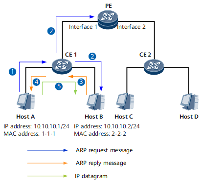
Figure 2 illustrates how ARP is implemented within a network segment, by using IP datagram transmission from Host A to Host B as an example.
Host A searches its ARP table and does not find the mapping between the IP and MAC addresses of Host B. Host A then sends an ARP request message for the MAC address of Host B. In this ARP request message, the source IP and MAC addresses are respectively the IP and MAC addresses of Host A, the destination IP and MAC addresses are respectively the IP address of Host B and 00-00-00-00-00-00, and the Ethernet source MAC address and Ethernet destination MAC address are respectively the MAC address of Host A and the broadcast MAC address.
After CE1 receives the ARP request message, CE1 broadcasts it on the network segment.
After Host B receives the ARP request message, Host B adds the MAC address of Host A to its ARP table and sends an ARP reply message to Host A. In this ARP reply message, the source IP and MAC addresses are respectively the IP and MAC addresses of Host B, the destination IP and MAC addresses are respectively the IP and MAC addresses of Host A, and the Ethernet source and destination MAC addresses are respectively the MAC addresses of Host B and Host A.
The PE also receives the ARP request message but discards it because the destination IP address in the ARP request message is not its own IP address.
CE1 receives the ARP reply message and forwards it to Host A.
After Host A receives the ARP reply message, Host A adds the MAC address of Host B to its ARP table and sends the IP datagrams to Host B.
- ARP implementation between different network segments
ARP messages are Layer 2 messages. Therefore, ARP is applicable only to devices on the same network segment. If two hosts on different network segments need to communicate, the source host sends IP datagrams to the default gateway, which in turns forwards the IP datagrams to the destination host. ARP implementation between different network segments involves separate ARP implementation within network segments. In this manner, hosts on different network segments can communicate.
The following examples show how ARP is implemented between different network segments, by using IP datagram transmission from Host A to Host C as an example.
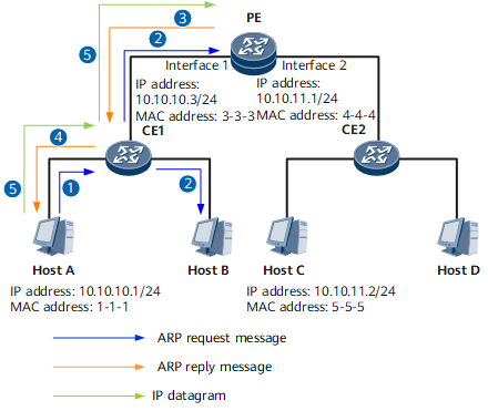
Figure 3 illustrates how ARP is implemented between Host A and the PE on the same network segment.
Host A searches its ARP table and does not find the mapping between the IP and MAC addresses of Interface 1 on the default gateway PE that connects to Host C. Host A then sends an ARP request message for the MAC address of the PE's Interface 1. In this ARP request message, the source IP and MAC addresses are respectively the IP and MAC addresses of Host A, the destination IP and MAC addresses are respectively the IP address of the PE's Interface 1 and 00-00-00-00-00-00, and the Ethernet source and destination MAC addresses are respectively the MAC address of Host A and the broadcast MAC address.
After CE1 receives the ARP request message, CE1 broadcasts it on the network segment.
After the PE receives the ARP request message, the PE adds the MAC address of Host A to its ARP table and sends an ARP reply message to Host A. In this ARP reply message, the source IP and MAC addresses are respectively the IP and MAC addresses of the PE's Interface 1, the destination IP and MAC addresses are respectively the IP and MAC addresses of Host A, and the Ethernet source and destination MAC addresses are respectively the MAC address of the PE's Interface 1 and the MAC address of Host A.
Host B also receives the ARP request message but discards it because the destination IP address in the ARP request message is not its own IP address.
CE1 receives the ARP reply message and forwards it to Host A.
After Host A receives the ARP reply message, Host A adds the MAC address of the PE's Interface 1 to its ARP table and sends the IP datagrams to the PE.
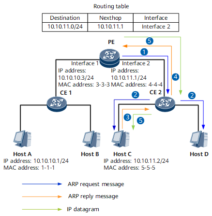
Figure 4 illustrates ARP implementation between the PE and Host C on the same network segment.
The PE searches its routing table and sends the IP datagrams from Interface 1 to Interface 2.
The PE searches its ARP table and does not find the mapping between the IP address and MAC address of Host C. Then, the PE sends an ARP request message for the MAC address of Host C. In this ARP request message, the source IP and MAC addresses are respectively the IP and MAC addresses of the PE's Interface 2, the destination IP and MAC addresses are respectively the Host C's IP address and 00-00-00-00-00-00, and the Ethernet source and destination MAC address are respectively the MAC address of Interface 2 on PE and the broadcast MAC address.
After CE2 receives the ARP request message, CE2 broadcasts it on the network segment.
After Host C receives the ARP request message, Host C adds the MAC address of the PE's Interface 2 to its ARP table and sends an ARP reply message to the PE. In this ARP reply message, the source IP and MAC addresses are respectively the IP and MAC addresses of Host C, the destination IP and MAC addresses are respectively the IP and MAC addresses of the PE's Interface 2, and the Ethernet source and destination MAC addresses are respectively the MAC address of Host C and the MAC address of Interface 2 on PE.
Host D also receives the ARP request message but discards it because the destination IP address in the ARP request message is not its own IP address.
CE2 receives the ARP reply message and forwards it to the PE.
After the PE receives the ARP reply message, the PE adds the MAC address of Host C to its ARP table and sends the IP datagrams to Host C.
So far, the IP datagram transmission from Host A to Host C is complete.
ARP request messages are broadcast, whereas ARP reply messages are unicast.
In ARP implementation, CE1 and CE2 transparently forward IP datagrams and do not modify them.