BGP Flow Specification Fundamentals
Basic Concepts
BGP Flow Specification route: BGP Flow Specification routes are defined in standard protocols. Each BGP Flow Specification route contains BGP network layer reachability information (NLRI) and extended community attributes, which carry traffic filtering rules and actions to be taken on matching traffic.
BGP Flow Specification peer relationship: A BGP Flow Specification peer relationship is established between the device that generates BGP Flow Specification routes and each network ingress to advertise the BGP Flow Specification routes. After receiving the BGP Flow Specification routes, the peer delivers preferred BGP Flow Specification routes to the forwarding plane. The routes are then converted into traffic policies that control attack traffic.
Mode |
Usage Scenario |
|---|---|
Dynamic BGP Flow Specification |
Dynamic BGP Flow Specification is used to control unknown attack traffic. A traffic analysis server is deployed to monitor the network and respond to the detection of attack traffic to improve network security. |
Static BGP Flow Specification |
Static BGP Flow Specification is used to control known or common attack traffic. BGP Flow Specification routes are manually created based on the characteristics of common attack traffic to prevent common attack traffic. |

BGP Flow Specification supports inter-AS transmission. If a BGP Flow Specification peer relationship is established between ingresses of two different ASs, BGP Flow Specification routes can be transmitted to the other AS so that attack traffic is controlled. This function confines attack traffic in a limited scope.
After a BGP Flow Specification peer receives a BGP Flow Specification route with the filtering rule of a destination address, the peer must verify the route. The route is considered valid only if it passes BGP Flow Specification route authentication.
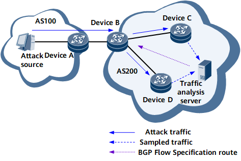
Dynamic BGP Flow Specification
- DeviceD and DeviceC sample traffic and send the traffic sample to the traffic analysis server.
- The analysis server checks the traffic sample in accordance with pre-configured rules to identify abnormal traffic.
- After identifying abnormal traffic, the server automatically generates a BGP Flow Specification route based on the traffic characteristics and sends the route to the ingress DeviceB.
- After receiving the route, DeviceB converts the route into a traffic policy to filter received traffic.
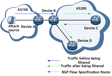
Static BGP Flow Specification
- A user configures a BGP Flow Specification route manually on DeviceC and configures a filtering rule and an action based on the characteristics of attack traffic.
- The BGP Flow Specification route is advertised to the ingress DeviceB.
- After receiving the route, DeviceB converts the route into a traffic policy to filter received traffic.
BGP Flow Specification Route Authentication
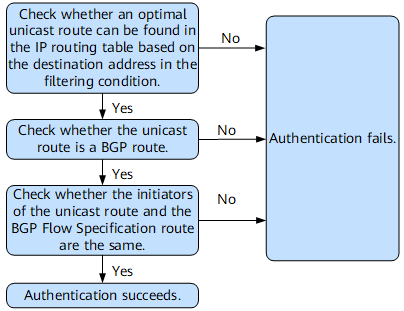
- Authentication mode 1: After receiving a BGP Flow Specification route with a destination address specified in a filtering rule, a device checks the validity of the route using rules described in Figure 3. The route is considered valid only if the authentication succeeds.
- Authentication mode 2: After receiving a BGP Flow Specification route with a destination address specified in a filtering rule, a device checks the validity of the route by checking whether the AS_Path attribute of the route carries the AS_Set or AS_Sequence field. The route is considered valid only if its AS_Path attribute does not carry the AS_Set or AS_Sequence field.
- If the authentication using mode 2 succeeds, the BGP Flow Specification route is considered valid, and the device does not attempt to authenticate the route using mode 1.
- If the authentication using mode 2 fails, the device attempts to authenticate the route using mode 1.
As mentioned previously, after receiving a BGP Flow Specification route with a destination address specified in a filtering rule, a BGP Flow Specification peer must verify the route. The route is considered valid only if it passes BGP Flow Specification route authentication. Figure 3 shows how BGP Flow Specification authentication works.
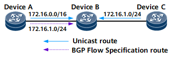
DeviceB searches its IP routing table and finds two unicast routes 172.16.0.0/16 and 172.16.1.0/24. After comparison, DeviceB finds that 172.16.1.0/24 is the optimal unicast route.
DeviceB checks the route 172.16.1.0/24 and finds that it is a BGP route.
The originator of the unicast route is DeviceC and the originator of the BGP Flow Specification route is DeviceA. The BGP Flow Specification route fails to be authenticated because the two originators are different.
On the NetEngine 8000 F, BGP Flow Specification route authentication can be disabled. If you want to filter traffic based on a specified address prefix, but the BGP Flow Specification route that carries the filtering rule cannot be authenticated, disable BGP Flow Specification route authentication.
BGP Flow Specification implementation on a private network is similar to that on a public network, except that the BGP Flow Specification peer relationship is a VPN peer relationship and the deployment is different on the private network.