VPLS PW Redundancy for Protecting Unicast Services
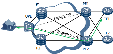
Figure 1 illustrates an application of VPLS PW redundancy for protecting unicast services, such as high-speed internet (HSI) or Voice over Internet Protocol (VoIP) services, on a virtual leased line (VLL) accessing virtual private LAN service (VPLS) network.
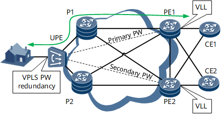
Authentication servers CE1 and CE2 are each dual-homed to PE1 and PE2 using the E-Trunk mechanism. A UPE connects the user end to PEs. The link between the UPE and PE1 and the link between the UPE and PE2 back up each other.
In this networking, PE1 and PE2 can determine their master/backup status through E-Trunk negotiation. Therefore, the UPE can use the independent PW redundancy mode to determine the active/standby PW status based on the master/backup status of PE1 and PE2. Upon detecting that the primary PW fails, the UPE rapidly switches traffic to the secondary PW and instructs PE2 to work as the master PE. After the E-Trunk mechanism detects that the primary PW fails, it switches traffic to the secondary AC link.
Figure 1 shows how service traffic transmits when no fault occurs. The following describes how VPLS PW redundancy protects traffic after a fault occurs.

The master/slave and independent VPLS PW redundancy modes protect services in different ways. The following describes the differences between the two modes in terms of service protection.
Network-Side Failure
Two levels of protection can be provided to protect services against network-side faults:
If a network-side fault occurs, LSPs or TE tunnels first detect the fault and switch traffic to other tunnels. If tunnel protection is unavailable or fails, PW redundancy is required to protect traffic. A bypass PW needs to be configured between PE1 and PE2 for PW redundancy.
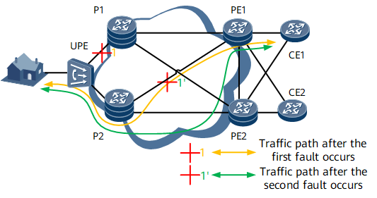
LSP or TE tunnel protection: After a network-side fault occurs, routes converge, and the LSP carrying the primary PW switches to a new route. Figure 2 shows how traffic is switched.
After the fault is rectified, routes re-converge, and the LSP carrying the primary PW switches to a new route.
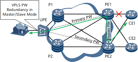
PW redundancy: If LSP or TE tunnel switching fails, traffic is switched to the secondary PW. Figure 3 shows how traffic is switched.
After the fault is rectified, traffic will be switched back based on preset switchback policies.
Bypass PWs are required for PW redundancy to transmit traffic between PE1 and PE2.
PE1 Failure
Figure 4 shows how traffic is switched if PE1 fails.
PE2 becomes the master and PE1 becomes the backup after E-Trunk negotiation. The UPE is informed of the switchover. Upon detecting that the primary PW fails, the UPE clears MAC addresses learned from the primary PW and switches traffic to the secondary PW.
Switchback: After PE1 recovers, PE1 becomes the master through E-Trunk negotiation. Upon detecting PE1 and PE2 status changes, the UPE clears MAC addresses learned from PE2 and relearns MAC addresses by broadcasting.
Failure of the Primary AC Link
The following describes how traffic is switched if the link between PE1 and CE1 fails:
In independent mode
After the primary AC link between CE1 and PE1 fails, PE2 works as the master after E-Trunk negotiation. The UPE is informed of the switchover. The UPE detects that the primary AC link fails and switches traffic to the secondary PW.
After the link between CE1 and PE1 recovers, PE1 becomes the master after E-Trunk negotiation. Upon detecting PE1 and PE2 status changes, the UPE clears MAC addresses learned from PE2 and relearns MAC addresses by broadcasting.
Figure 5 Protecting services against failures of the primary AC link in independent VPLS PW redundancy mode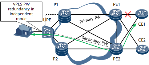
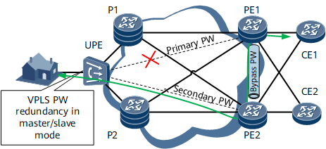
In master/slave mode
After the primary AC link between CE1 and PE1 fails, PE2 works as the master after E-Trunk negotiation. The PW forwarding status on the UPE remains unchanged.
After the fault is rectified, PE1 becomes the master after the master/backup status is negotiated in the E-Trunk. The UPE, however, can detect that PE1 becomes the master and PE2 becomes the backup. However, the PW status is not switched on the UPE.
Figure 6 Protecting services against failures of the primary AC link in master/slave VPLS PW redundancy mode