Rapid VRRP Switchback
Principles
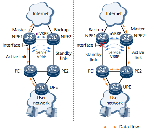
On the network shown in Figure 1, VRRP-enabled NPEs are connected to user-side PEs through active and standby links. User traffic travels over the active link to the master NPE1, and NPE1 forwards user traffic to the Internet. If NPE1 is working properly, user traffic travels over the path UPE -> PE1 -> NPE1. If the active link or NPE1's interface 1 tracked by the VRRP group fails, an active/standby link switchover and a master/backup VRRP switchover are implemented. After the switchovers, user traffic switches to the path UPE -> PE1 -> PE2 -> NPE2. After the fault is rectified, an active/standby link switchback and a master/backup VRRP switchback are implemented. If the active link becomes active before the original master device restores the Master state, user traffic is interrupted.
To prevent user traffic interruptions, the rapid VRRP switchback function is used to allow the original master device to switch from the Backup state to the Master state immediately after the fault is rectified.
Related Concept
A VRRP switchback is a process during which the original master device switches its status from Backup to Master after a fault is rectified.
Implementation
- A common VRRP group is configured on NPE1 and NPE2 that run VRRP. An mVRRP group is configured on directly connected interfaces of NPE1 and NPE2. The common VRRP group is bound to the mVRRP group and becomes a service VRRP group. The mVRRP group determines the master/backup status of the service VRRP group.
- NPE1 has a VRRP priority of 120 and works in the Master state in the mVRRP group.
- NPE2 has a VRRP priority of 100 and works in the Backup state in the mVRRP group.
- NPE1 tracks interface 1 and reduces its priority by 40 if interface 1 goes Down.
The rapid VRRP switchback process is as follows:
- If NPE1 is working properly, NPE1 periodically sends VRRP Advertisement packets to notify NPE2 of the Master state. NPE1 tracks interface 1 connected to the active link.
- If the active link or interface 1 fails, interface 1 goes Down. The service VRRP group on NPE1 is in the Initialize state. NPE1 reduces its mVRRP priority to 80 (120 - 40). As a result, the mVRRP priority of NPE2 is higher than that of NPE1, and NPE2 immediately preempts the Master state. NPE2 then sends a VRRP Advertisement packet carrying a higher priority than that of NPE1. After receiving the packet, the mVRRP group on NPE1 stops sending VRRP Advertisement packets and enters the Backup state. The status of the service VRRP group is the same as that of the mVRRP group on NPE2. User traffic switches to the path UPE -> PE1 -> PE2 -> NPE2.
- After the fault is rectified, interface 1 goes Up and NPE1 increases its VRRP priority to 120 (80 + 40). NPE1 immediately preempts the Master state and sends VRRP Advertisement packets to NPE2. User traffic switches back to the path UPE -> PE1 -> NPE1.

If rapid VRRP switchback is not configured and NPE1 restores its priority to 120, NPE1 has to wait until it receives VRRP Advertisement packets carrying a lower priority than its own priority from NPE2 before preempting the Master state.
- NPE1 then sends VRRP Advertisement packets carrying a higher priority than NPE2's priority. After receiving the VRRP Advertisement packets, NPE2 enters the Backup state. Both NPE1 and NPE2 restore their previous status.
Usage Scenario
- The master device in an mVRRP group tracks a VRRP-disabled interface or feature and reduces its VRRP priority if the interface or feature status becomes Down.
- Devices in a VRRP group are connected to user-side devices over the active and standby links.
- An active/standby link switchback is implemented quicker than a master/backup VRRP switchback.
Benefits
Rapid VRRP switchback speeds up a VRRP switchback after a fault is rectified.