Application of VPLS in Residential Services
Service Overview
Residential services, such as HSI, VoIP, and broadband TV (BTV) are usually carried over carriers' MANs.
Traditional ATM and FR technologies provide only P2P connections. In addition, those network types have disadvantages, such as high construction costs, low speed, and complex deployment. The development of IP has led to the Ethernet-based VPLS technology that can provide P2MP connections to transparently transmit residential services. Meanwhile, VPLS networks have advantages, such as low construction costs, high speed, and simple configuration. Therefore, current MANs generally use VPLS to transmit user traffic.
Networking Description
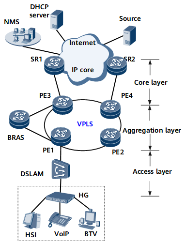
Residential services are transmitted to the Internet over the access layer, aggregation layer, and core layer of a MAN. Figure 1 shows the typical networking for residential services. On this network:
HSI services access the Internet over the MAN.
VoIP services request IP addresses from the Dynamic Host Configuration Protocol (DHCP) server over the MAN.
BTV multicast members apply for BTV services from multicast sources over the MAN.
Feature Deployment
VPLS is configured on PEs to transparently transmit traffic between them. From the perspective of residential users, the public network is like a Layer 2 switch. Figure 1 uses LDP VPLS as an example to show VPLS configuration:
Access-layer devices
VLANs are configured to differentiate different types of users.
Multicast VLAN and Internet Group Management Protocol (IGMP) snooping are configured to transmit multicast services.
Aggregation-layer devices
IGPs are configured on PEs so that these PEs can communicate with each other.
Basic MPLS functions are configured on PEs so that these PEs can establish remote LDP sessions. MPLS TE tunnels are established between PEs, and TE fast reroute (FRR) is configured on these PEs.
MPLS L2VPN and VSIs are configured on PEs.
Authentication and accounting features are configured on BRASs so that BRASs can terminate HSI services.
A VPLS daisy chain is deployed on PEs to transmit multicast services.
Core-layer devices
IGPs are configured on SRs so that these SRs can communicate with each other.
Basic MPLS functions are configured on SRs.
DHCP relay is configured on SRs, allowing VoIP users to obtain IP addresses from DHCP servers.
Layer 3 multicast features are configured on SRs so that these SRs can communicate with multicast sources.