ERPS Layer 2 Protocol Tunneling Application
Redundant links are used on an Ethernet switching network to provide link backup and enhance network reliability. The use of redundant links, however, may produce loops, causing broadcast storms and rendering the MAC address table unstable. As a result, the communication quality deteriorates, and communication services may be interrupted.
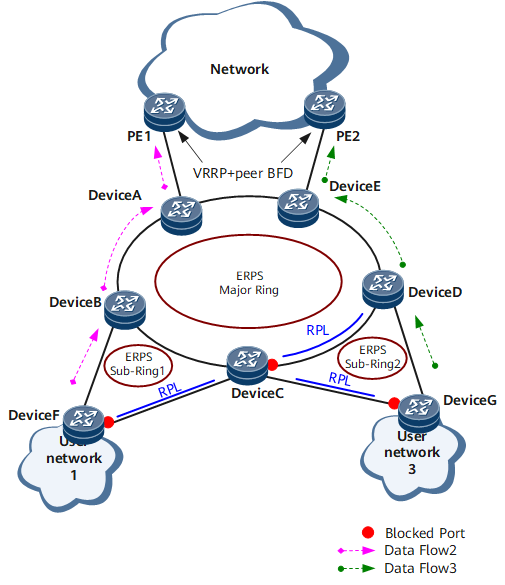
To prevent loops caused by redundant links, enable ERPS on the nodes of the ring network. ERPS is a Layer 2 loop-breaking protocol defined by the ITU-T. It boasts of fast convergence, implementing convergence within 50 ms.
On the network shown in Figure 1, Device A through Device E constitute a major ring; Device A, Device C, and Device F constitute a sub-ring; Device C, Device D, and Device G constitute another sub-ring. The ERPS ring network resides at the aggregation layer, and therefore is an aggregation ring. The aggregation ring aggregates Layer 2 services to the upstream Layer 3 network, providing Layer 2 protection switching. VLANIF interfaces are configured on Device A and Device E for Layer 3 access. VRRP is configured on the VLANIF interfaces to implement the virtual gateway function, and peer BFD is enabled for fast fault detection and accordingly fast VRRP switching.
If ERPS multi-instances are configured, ERPS is implemented in the same manner as that in Figure 1, except that two logical ERPS rings are configured on the physical ring in Figure 1, and each logical ERPS ring has its switches, port roles, and control VLANs independently configured.