Application Scenarios for Routing Policies
Specific Route Filtering
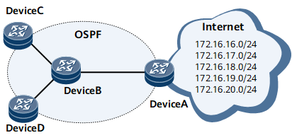
On the OSPF-enabled network shown in Figure 1, Device A receives routes from the Internet and advertises some of the routes to Device B.
Device A advertises only routes 172.16.17.0/24, 172.16.18.0/24, and 172.16.19.0/24 to Device B.
Device C accepts only the route 172.16.18.0/24.
Device D accepts all the routes advertised by Device B.
Use IP prefix lists
- Configure an IP prefix list for Device A and configure the IP prefix list as an export policy on Device A for OSPF.
- Configure another IP prefix list for Device C and configure the IP prefix list as an import policy on Device C for OSPF.
Use route-policies
- Configure a route-policy (the matching rules can be the IP prefix list, cost, or route tag) for Device A and configure the route-policy as an export policy on Device A for OSPF.
- Configure another route-policy on Device C and configure the route-policy as an import policy on Device C for OSPF.
Compared with an IP prefix list, a route-policy can change route attributes and control routes more flexibly, but it is more complex to configure.
Transparent Transmission of Routes of Other Protocols Through an OSPF AS
On the network shown in Figure 2, an AS runs OSPF and functions as a transit AS for other areas. Routes from the IS-IS area connected to Device A need to be transparently transmitted through the OSPF AS to the IS-IS area connected to Device D. Routes from the RIP-2 area connected to Device B need to be transparently transmitted through the OSPF AS to the RIP-2 area connected to Device C.
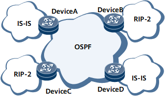
To meet the preceding requirements, configure a route-policy for Device A to set a tag for the imported IS-IS routes. Device D identifies the IS-IS routes from OSPF routes based on the tag.
Routing Policy Application in Inter-AS VPN Option C
On the network shown in Figure 3, CE1 and CE2 communicate with each other through inter-AS VPN Option C.

- When an ASBR advertises the routes received from a PE in the same AS to the peer ASBR, the ASBR allocates MPLS labels to the routes using a route-policy.
- When an ASBR advertises labeled IPv4 routes to a PE in the same AS, the ASBR reallocates MPLS labels to the routes using another route-policy.
In addition, to control route transmission between different VPN instances on a PE, configure a route-policy for the PE and configure the route-policy as an import or export policy for the VPN instances.
Application of BGP to IGP
On the network shown in Figure 4, Device A and Device B are aggregation devices on a backbone network, and Device C and Device D are egress devices of a metropolitan area network (MAN). BGP peer relationships are established between Device A and Device C as well as between Device B and Device D. External routes are advertised to the MAN using BGP. The MAN runs OSPF to implement interworking.
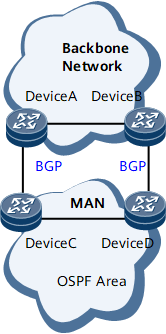
To enable devices on the MAN to access the backbone network, Device C and Device D need to import routes. When OSPF imports BGP routes, a routing policy can be configured to control the number of imported routes based on private attributes (such as the community) of the imported BGP routes or modify the cost of the imported routes to control the MAN egress traffic.