IPRAN Gateway Protection Solution
Service Overview
NodeBs and radio network controllers (RNCs) on an IP radio access network (IPRAN) do not have dynamic routing capabilities. Static routes must be configured to allow NodeBs to communicate with access aggregation gateways (AGGs) and allow RNCs to communicate with radio service gateways (RSGs) at the aggregation level. To ensure that various value-added services, such as voice, video, and cloud computing, are not interrupted on mobile bearer networks, a VRRP group can be deployed to implement gateway redundancy. When the master device in a VRRP group goes Down, a backup device takes over, ensuring normal service transmission and enhancing device reliability at the aggregation layer.
Networking Description
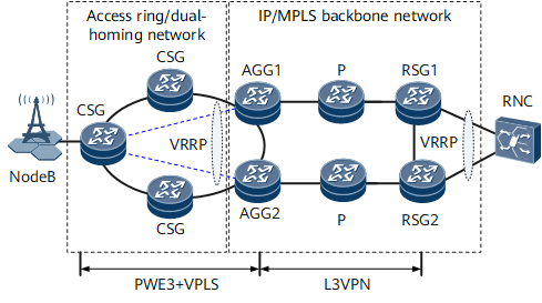
Figure 1 shows the network for the IPRAN gateway protection solution. A NodeB is connected to AGGs over an access ring or is dual-homed to two AGGs. The cell site gateways (CSGs) and AGGs are connected using the Pseudowire Emulation Edge-to-Edge (PWE3) technology, which ensures connection reliability. Two VRRP groups can be configured on the AGGs and RSGs to implement gateway backup for the NodeB and RNC, respectively.
Feature Deployment
Table 1 describes VRRP-based gateway protection applications on an IPRAN.
Network Layer |
Feature Deployment |
Usage Scenario |
|---|---|---|
Deploy VRRP groups on AGGs to implement gateway backup for the NodeB. |
Associate an mVRRP group with a service VRRP group. |
To meet various service demands, different VRRP groups can be configured on AGGs to provide gateway functions for different user groups. Each VRRP group maintains its own state machine, leading to transmission of multiple VRRP packets on the AGGs. These packets use a significant amount of bandwidth when traversing the access network. To simplify VRRP operations and reduce bandwidth consumption, an mVRRP group can be associated with service VRRP groups on AGGs. During this process, service VRRP groups function as gateways for the NodeB and are associated with the mVRRP group. The mVRRP group processes VRRP Advertisement packets and determines the master/backup status of the associated service VRRP group. |
Associate an mVRRP group with a BFD session. |
By default, when a VRRP group detects that the master device goes Down, the backup device attempts to preempt the Master state after 3 seconds (three times the interval at which VRRP Advertisement packets are broadcast). During this period, no master device forwards user traffic, which leads to traffic forwarding interruptions. BFD can detect link faults in milliseconds. After an mVRRP group is associated with a BFD session and BFD detects a fault, a master/backup VRRP switchover is implemented, preventing user traffic loss. When the master device goes Down, the BFD module instructs the backup device in the mVRRP group to preempt the Master state and take over traffic. The status of the service VRRP group associated with the mVRRP group changes accordingly. This implementation reduces service interruptions. |
|
Associate direct network segment routes with a service VRRP group. |
During the traffic transmission between the NodeB and RNC, user-to-network and network-to-user traffic may travel through different paths, causing network operation, maintenance, and management difficulties. For example, the NodeB sends traffic destined for the RNC through the master AGG. The RNC sends traffic destined for the NodeB through the backup AGG. This implementation increases traffic monitoring costs. Association between direct network segment routes and a service VRRP group can be deployed to ensure that user-to-network and network-to-user traffic travels through the same path. |
|
Deploy VRRP groups on RSGs to implement gateway backup for the RNC. |
Deploy basic VRRP functions. |
RSGs provide gateway functions for the RNC. Basic VRRP functions can be configured on the RSGs to implement gateway backup. In normal circumstances, the master device forwards user traffic. When the master device goes Down, the backup device takes over. |
Associate a VRRP group with a BFD session. |
A VRRP group can be associated with a BFD session to implement a rapid master/backup VRRP switchover when BFD detects a fault. When the master device goes Down, the BFD module instructs the backup device in the VRRP group to preempt the Master state and take over traffic. This implementation reduces service interruptions. |
|
Associate direct network segment routes with a VRRP group. |
Direct network segment routes can be associated with a VRRP group to ensure the same path for both user-to-network and network-to-user traffic between the NodeB and RNC. |
Protection Switching Process
AGG1 and RSG1 are deployed as master devices. The following describes user traffic path changes when AGG1 goes Down and after AGG1 recovers.
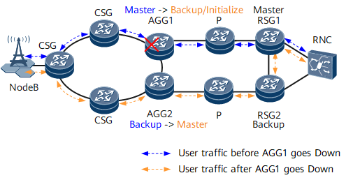
As shown in Figure 2, in normal circumstances, the NodeB sends traffic through the CSGs to AGG1 over the primary pseudo wire (PW). AGG1 forwards the traffic to RSG1 through the P device. Then, RSG1 forwards the traffic to the RNC. The path for user-to-network traffic is CSG -> AGG1 -> P -> RSG1 -> RNC, and the path for network-to-user traffic is RNC -> RSG1 -> P -> AGG1 -> CSG.
When AGG1 goes Down, a primary/secondary PW switchover is performed. Traffic sent from the NodeB goes through the CSGs to AGG2 through the new primary PW. AGG2 forwards the traffic to RSG1 through the P device and RSG2. Then, RSG1 sends the traffic to the RNC. The path for user-to-network traffic is CSG -> AGG2 -> P -> RSG2 -> RSG1 -> RNC, and the path for network-to-user traffic is RNC -> RSG1 -> RSG2 -> P -> AGG2 -> CSG.
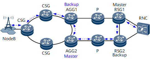
As shown in Figure 3, when AGG1 recovers, a primary/secondary PW switchover is performed, but a master/backup switchover is not performed in the mVRRP group. Therefore, traffic sent from the NodeB goes through the CSGs and AGG1 to AGG2 over the previous primary PW. AGG2 forwards the traffic to RSG1 through the P device and RSG2. RSG1 then forwards the traffic to the RNC. The path for user-to-network traffic is CSG -> AGG1 -> AGG2 -> P -> RSG2 -> RSG1 -> RNC, and the path for network-to-user traffic is RNC -> RSG1 -> RSG2 -> P -> AGG2 -> AGG1 -> CSG.
When AGG1 recovers, it becomes the master device after a specified preemption delay elapses. AGG2 then becomes the backup device. Traffic sent from the NodeB goes through the CSGs to AGG1 over the previous primary PW. AGG1 sends the traffic to RSG1 through the P device. RSG1 then sends the traffic to the RNC. The path for user-to-network traffic is CSG -> AGG1 -> P -> RSG1 -> RNC, and the path for network-to-user traffic is RNC -> RSG1 -> P -> AGG1 -> CSG.