Multicast VLAN
Background
In traditional multicast on-demand mode, if users in different VLANs require the same multicast flow, an upstream device of a Layer 3 device must send a copy of the multicast flow for each user. This mode wastes bandwidth and imposes additional burdens on the upstream device.
The multicast VLAN function can be used to address this problem. With the help of IGMP snooping, the multicast VLAN function moves the multicast replication point downstream to an edge device, so that only one multicast flow is replicated on an upstream device for different VLANs that require the same flow.
For example, on the network shown in Figure 1, the CE is a Layer 2 device, and the PE is an upstream device of the CE. Users in VLANs 11 and 12 require the same multicast flow from the CE. After multicast VLAN 3 is configured on the CE, the PE sends only one copy of the multicast flow to VLAN 3. The CE then sends a copy of the multicast flow to VLAN 11 and VLAN 22. The PE no longer needs to send identical multicast data flows downstream. This mode saves network bandwidth and relieves the load on the PE.
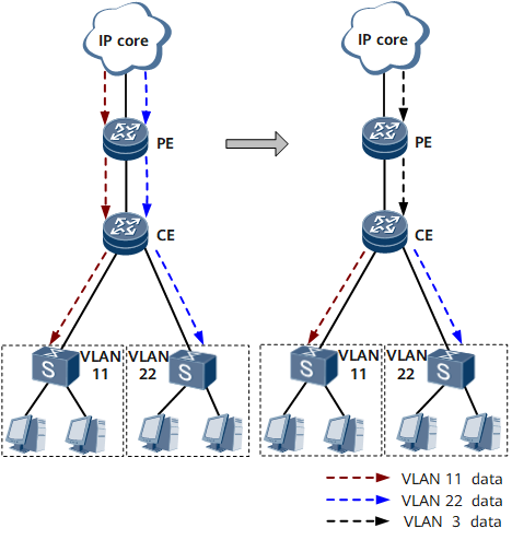
The following uses the network shown in Figure 1 as an example to describe why multicast VLAN requires IGMP snooping proxy to be enabled.
If IGMP snooping proxy is not enabled on VLAN 3 and users in different VLANs want to join the same group, the CE forwards each user's IGMP Report message to the PE. Similarly, if users in different VLANs leave the same group, the CE also needs to forward each user's IGMP Leave message to the PE.
If IGMP snooping proxy is enabled on VLAN 3 and users in different VLANs want to join the same group, the CE forwards only one IGMP Report message to the PE. If the last member of the group leaves, the CE sends an IGMP Leave message to the PE. This reduces network-side bandwidth consumption on the CE and performance pressure on the PE.
Related Concepts
The following concepts are involved in the multicast VLAN function:
Multicast VLAN: is a VLAN to which the interface connected to a multicast source belongs. A multicast VLAN is used to aggregate multicast flows.
User VLAN: is a VLAN to which a group member host belongs. A user VLAN is used to receive multicast flows from a multicast VLAN.
One multicast VLAN can be bound to multiple user VLANs.
After the multicast VLAN function is configured on a device, the device receives multicast traffic through multicast VLANs and sends the multicast traffic to users through user VLANs.
Implementation
The multicast VLAN implementation process can be divided into two parts:
Protocol packet forwarding
After the user VLAN tag in an IGMP Report message is replaced with a corresponding multicast VLAN tag, the message is sent out through a router port of the multicast VLAN.
After the multicast VLAN tag in an IGMP Query message is replaced with a corresponding user VLAN tag, the message is sent out through a member port of the user VLAN.
Entries learned through IGMP snooping in user VLANs are added to the table of the multicast VLAN.
Multicast data forwarding
After receiving a multicast data packet from an upstream device, a Layer 2 device searches its multicast forwarding table for a matching entry.
- If a matching forwarding entry exists, the Layer 2 device will identify the downstream ports and their VLAN IDs, replicate the multicast data packet on each downstream port, and send a copy of the packet to user VLANs.
- If no matching forwarding entry exists, the Layer 2 device will discard the multicast data packet.
Other Functions
A user VLAN allows you to configure the querier election function. The following uses the network shown in Figure 2 as an example to describe the querier election function.
- A CE connects to Router A through both Router B and Router C, which improves the reliability of data transmission. The querier function is enabled on Router B and Router C.
- Multicast VLAN is enabled on Router B and Router C. VLAN 11 is a multicast VLAN, and VLAN 22 is a user VLAN.
Both Router B and Router C in VLAN 11 are connected to VLAN 22. As a result, VLAN 22 will receive two identical copies for the same requested multicast flow from Router B and Router C, causing data redundancy.
To address this problem, configure querier election on Router B and Router C in the user VLAN and specify one of them to send Query messages and forward multicast data flows. In this manner, VLAN 22 receives only one copy of a multicast data flow from the upstream Router A over VLAN 11.
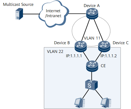
A querier is elected as follows in a user VLAN (the network shown in Figure 2 is used as an example):
- After receiving a Query message from Router A, Router B and Router C replace the source IP address of the Query message with their own local source IP address (1.1.1.1 for Router B and 1.1.1.2 for Router C).
- Router B and Router C exchange Query messages. Based on the querier election algorithm, Router B with a smaller source IP address is elected as a querier.
- As a querier, Router B generates a forwarding entry after receiving a Join message from VLAN 22, while Router C does not generate a forwarding entry. Then, multicast data flows from upstream devices are forwarded by Router B to VLAN 22.
Deployment Scenarios
The multicast VLAN function can be used on VLANs.
Benefits
- Reduced bandwidth consumption
- Reduced workloads for Layer 3 devices
- Simplified management of multicast sources and multicast group members