mLDP
The multipoint extensions for Label Distribution Protocol (mLDP) transmits multicast services over IP or Multiprotocol Label Switching (MPLS) backbone networks, which simplifies network deployment.
Background
Traditional core and backbone networks run IP and MPLS to flexibly transmit unicast packets and provide high reliability and traffic engineering (TE) capabilities.
The proliferation of applications, such as IPTV, multimedia conference, and massively multiplayer online role-playing games (MMORPGs), amplifies demands on multicast transmission over IP/MPLS networks. The existing P2P MPLS technology requires a transmit end to deliver the same data packet to each receive end, which wastes network bandwidth resources.
The point-to-multipoint (P2MP) Label Distribution Protocol (LDP) technique defined in mLDP can be used to address the preceding problem. P2MP LDP extends the MPLS LDP protocol to meet P2MP transmission requirements and uses bandwidth resources much more efficiently.
Related Concepts
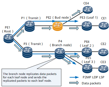
Table 1 describes the nodes used on the P2MP LDP network shown in Figure 1.
Item |
Description |
Example |
|---|---|---|
Root node |
An ingress on a P2MP LDP LSP. The ingress initiates LSP calculation and establishment. The ingress pushes a label into each multicast packet before forwarding it along an established LSP. |
PE1 |
Transit node |
An intermediate node that swaps an incoming label for an outgoing label in each MPLS packet. A branch node may function as a transit node. |
P1 and P3 |
Leaf node |
A destination node on a P2MP LDP LSP. |
PE3, PE4, and PE5 |
Bud node |
An egress of a sub-LSP and transit node of other sub-LSPs. The bud node is connected to a customer edge (CE) and is functioning as an egress. |
PE2 |
Branch node |
A node from which LSP branches (sub-LSP) start. A branch node replicates packets and swaps an incoming label for an outgoing label in each packet before forwarding it to each leaf node. |
P4 |
Implementation
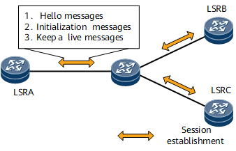
Nodes negotiate the P2MP LDP capability with each other.
mLDP enables a node to negotiate the P2MP LDP capability with a peer node and establish an mLDP session with the peer node.
A P2MP LDP LSP is established.
Each leaf and transit node sends a Label Mapping message upstream until the root node receives a Label Mapping message downstream. The root node then establishes a P2MP LDP LSP with sub-LSPs that are destined for leaf nodes.
A node deletes a P2MP LDP LSP.
A node of a specific type uses a specific rule to delete an LSP, which minimizes the service interruptions.
-
If the network topology or link cost changes, the P2MP LDP LSP updates automatically based on a specified rule, which ensures uninterrupted service transmission.
P2MP LDP Capability Negotiation

P2MP LDP LSP Establishment
Field |
Description |
|---|---|
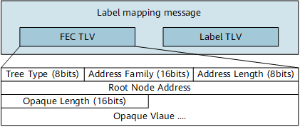
Tree Type |
mLDP LSP type:
|
Address Family |
Address family to which a root node's IP address belongs |
Address Length |
Length of a root node's IP address |
Root Node Address |
Root node's IP address, which is manually designated |
Opaque Length |
Length of the opaque value |
Opaque Value |
Value that identifies a specific P2MP LSP on a root node and carries information about the root (also called ingress) and leaf nodes on the P2MP LSP |
- Leaf node: manually specified. When configuring a leaf node, you must also specify the root node IP address and the opaque value.
- Transit node: any node that can receive P2MP Label Mapping messages and whose LSR ID is different from the LSR IDs of the root nodes.
- Root node: a node whose host address is the same as the root node's IP address carried in a P2MP LDP FEC.
Leaf and transit nodes select their upstream nodes.
A node that is the next hop in a preferred route to the root node is selected as an upstream node. The label advertisement mode is downstream unsolicited (DU) for a P2MP LDP LSP. This mode requires each leaf and transit node to select upstream nodes and send Label Mapping messages to the upstream nodes.
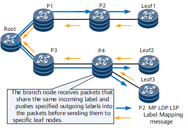
Nodes send Label Mapping messages to upstream nodes and generate forwarding entries.
As shown in Figure 5, each node performs the following operations before completing the LSP establishment:- Leaf node: sends a Label Mapping message to its upstream node and generates a forwarding entry.
- Transit node: receives a Label Mapping message from its downstream node and checks whether it has sent a Label Mapping message to its upstream node:
- If the transit node has sent no Label Mapping message to any upstream nodes, it looks up the routing table and finds an upstream node. If the upstream and downstream nodes of the transit node have different IP addresses, the transit node sends a Label Mapping message to the upstream node. If the upstream and downstream nodes of the transit node have the same IP address, the transit node does not send a Label Mapping message.
- If the transit node has sent a Label Mapping message to its upstream node, it does not send a Label Mapping message again.
The transit node then generates a forwarding entry.
- Root node: receives a Label Mapping message from its downstream node and generates a forwarding entry.
A P2MPL LDP LSP is then established.
P2MP LDP LSP Deletion
Leaf node
A leaf node sends a Label Withdraw message to an upstream node. After the upstream node receives the message, it replies with a Label Release message to instruct the leaf node to tear down the sub-LSP. If the upstream node has only the leaf node as a downstream node, the upstream node sends the Label Withdraw message to its upstream node. If the upstream node has another downstream node, the upstream node does not send the Label Withdraw message.
Transit node
If a transit node or an LDP session between a transit node and its upstream node fails or a user manually deletes the transit node configuration, the upstream node of the transit node deletes the sub-LSPs that pass through the transit node. If the upstream node has only the transit node as a downstream node, the upstream node sends the Label Withdraw message to its upstream node. If the upstream node has another downstream node, the upstream node does not send the Label Withdraw message.
Root node
If a root node fails or a user manually deletes the LSP configuration on the root node, the root node deletes the whole LSP.
P2MP LDP LSP Update
A leaf node dynamically joins a P2MP LDP LSP.
A leaf node negotiates a P2MP LDP session with its upstream node. After the session is established, the leaf node assigns a label to its upstream node. The upstream node directly adds the sub-LSP to the leaf node to the LSP and updates the forwarding entry for the sub-LSP.
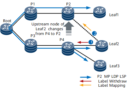
An upstream node is modified.
As shown in Figure 6, the upstream node of Leaf 2 is changed from P4 to P2. To prevent LSP loops, Leaf 2 sends a Label Withdraw message to P4. Upon receipt, P4 deletes the sub-LSP to Leaf 2 and deletes the forwarding entry for the sub-LSP. Leaf 2 then sends a Label Mapping message to P2. Upon receipt, P2 establishes a sub-LSP to Leaf 2 and generates a forwarding entry.The make-before-break (MBB) mechanism is used.
If the optimal path between an LSR and the root node changes after a link recovers or the link cost changes, the LSR re-selects its upstream node, which leads to a P2MP LDP LSP update. This process causes packet loss. mLDP uses the MBB mechanism to minimize packet loss during the P2MP LDP LSP update. The MBB mechanism enables the LSR to establish a new LSP before tearing down the original LSP. This means that although the LSR sends a Label Mapping message upstream, the LSR retains the original LSP. After the upstream node sends an MBB Notification message informing that a new LSP is successfully established, the LSR tears down the original LSP.
Other Usage
mLDP P2MP LSPs can transmit services on next generation (NG) multicast VPN (MVPN) and multicast VPLS networks. In the MVPN or multicast VPLS scenario, NG MVPN signaling or multicast VPLS signaling triggers the establishment of mLDP P2MP LSPs. There is no need to manually configure leaf nodes.
Usage Scenarios
- IPTV services are transmitted over an IP/MPLS backbone network.
- Multicast virtual private network (VPN) services are transmitted.
- The virtual private LAN service (VPLS) is transmitted along a P2MP LDP LSP.
Benefits
- Core nodes on the IP/MPLS backbone network can transmit multicast services, without Protocol Independent Multicast (PIM) configured, which simplifies network deployment.
- Uniform MPLS control and forwarding planes are provided for the IP/MPLS backbone network. The IP/MPLS backbone network can transmit both unicast and multicast VPN traffic.