Application Scenarios for Static Routes
In Figure 1, the network topology is simple, and network communication can be implemented through static routes. You need to specify an address for each physical network, identify indirectly connected physical networks for each device, and configure static routes for indirectly connected physical networks.
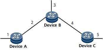
In this example, static routes to networks 3, 4, and 5 need to be configured on Device A; static routes to networks 1 and 5 need to be configured on Device B; static routes to networks 1, 2, and 3 need to be configured on Device C.
Default Static Route
Default routes are a special kind of routes, and default static routes are manually configured. The default route is used when no matched entry is available in the routing table. In an IPv4 routing table, the destination address and subnet mask of a default route are both 0.0.0.0. In an IPv6 routing table, the destination address and prefix of a default route are both ::.
If the destination address of a packet does not match any entry in the routing table, the device selects the default route to forward this packet. If no default route exists and the destination address of the packet does not match any entry in the routing table, the packet is discarded. An Internet Control Message Protocol (ICMP) packet is then sent, informing the originating host that the destination host or network is unreachable.
The static route with the destination address and mask 0s (0.0.0.0 0.0.0.0) configured using the ip route-static command is a default route intended to simplify network configuration.
In Figure 1, because the next hop of the packets from Device A to networks 3, 4, and 5 is Device B, a default route can be configured on Device A to replace the three static routes destined for networks 3, 4, and 5. Similarly, only a default route from Device C to Device B needs to be configured to replace the three static routes destined for networks 1, 2, and 3.
Floating Static Routes
Different static routes can be configured with different priorities so that routing management policies can be flexibly applied. Route backup can be implemented by specifying different priorities for multiple routes to the same destination.
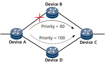
In Figure 2, there are two static routes from Device A to Device C. In most cases, the only Active route is the static route with Device B as the next hop in the routing table because it has a higher priority. The other static route with Device D as the next hop functions as a backup route. The backup route is only activated to forward traffic if the primary link fails. After the primary link recovers, the static route with Device B as the next hop becomes Active to take over the traffic. Therefore, the backup route is also called a floating static route. The floating static route becomes ineffective if a fault occurs on the link between Device B and Device C.
Load Balancing Among Static Routes
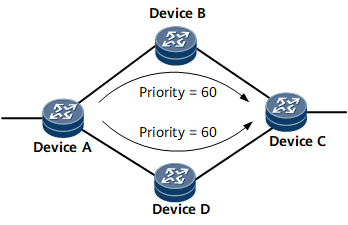
Routes to the same destination with the same priority can be used to load-balance traffic.
As shown in Figure 3, there are two static routes with the same priority from Device A to Device C. The two routes both exist in the routing table and forward traffic at the same time.
FRR for Static Routes
When routes are delivered to the routing management (RM) module, the optimal route is delivered with a backup route. If the optimal route fails, traffic is immediately switched to the backup route, minimizing traffic loss.
You need to configure two routes with the same prefix but different priorities to implement FRR. The route with the higher priority is the primary route, and the route with the lower priority is the backup route. FRR is implemented only on static routes that are manually configured. That is, FRR is not implemented on recursive next hops.