Basic Concepts
Maintenance Domain
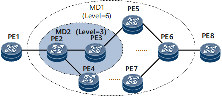
MDs are discrete areas within which connectivity fault detection is enabled. The boundary of an MD is determined by MEPs configured on interfaces. An MD is identified by an MD name.
To help locate faults, MDs are divided into levels 0 through 7. A larger value indicates a higher level, and an MD covers a larger area. One MD can be tangential to another MD. Tangential MDs share a single device and this device has one interface in each of the MDs. A lower level MD can be nested in a higher level MD. An MD must be fully nested in another MD, and the two MDs cannot overlap. A higher level MD cannot be nested in a lower level MD.
Classifying MDs based on levels facilitates fault diagnosis. MD2 is nested in MD1 on the network shown in Figure 1. If a fault occurs in MD1, PE2 through PE6 and all the links between the PEs are checked. If no fault is detected in MD2, PE2, PE3, and PE4 are working properly. This means that the fault is on PE5, PE6, or PE7 or on a link between these PEs.
In actual network scenarios, a nested MD can monitor the connectivity of the higher level MD in which it is nested. Level settings allow 802.1ag packets to transparently travel through a nested MD. For example, on the network shown in Figure 1, MD2 with the level set to 3 is nested in MD1 with the level set to 6. 802.1ag packets must transparently pass through MD2 to monitor the connectivity of MD1. The level setting allows 802.1ag packets to pass through MD2 to monitor the connectivity of MD1 but prevents 802.1ag packets that monitor MD2 connectivity from passing through MD1. Setting levels for MDs helps locate faults.
802.1ag packets are exchanged and CFM functions are implemented based on MDs. Properly planned MDs help a network administrator locate faults.
Default MD
A single default MD with the highest priority can be configured for each device according to Std 802.1ag-2007.
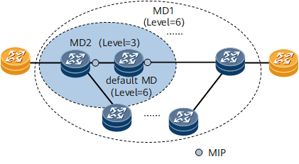
On the network shown in Figure 2, if default MDs with the same level as the higher level MDs are configured on devices in lower level MDs, MIPs are generated based on the default MDs to reply to requests sent by devices in higher level MDs. CFM detects topology changes and monitors the connectivity of both higher and lower level MDs.
The default MD must have a higher level than all MDs to which MEPs configured on the local device belong. The default MD must also be of the same level as a higher level MD. The default MD transmits high level request messages and generates MIPs to send responses.
Standard 802.1ag-2007 states that one default MD can be configured on each device and associated with multiple virtual local area networks (VLANs). VLAN interfaces can automatically generate MIPs based on the default MDs and a creation rule.
Maintenance Association
Multiple MAs can be configured in an MD as needed. Each MA contains MEPs. An MA is uniquely identified by an MD name and an MA name.
An MA serves a specific service such as VLAN. A MEP in an MA sends packets carrying tags of the specific service and receives packets sent by other MEPs in the MA.
Maintenance Association End Point
MEPs are located at the edge of an MD and MA. The service type and level of packets sent by a MEP are determined by the MD and MA to which the MEP belongs. A MEP processes packets at specific levels based on its own level. A MEP sends packets carrying its own level. If a MEP receives a packet carrying a level higher than its own, the MEP does not process the packet and loops it along the reverse path. If a MEP receives a packet carrying a level lower than or equal to its own, the MEP processes the packet.
A MEP is configured on an interface. The MEP level is equal to the MD level.
A MEP configured on an Ethernet CFM-enabled device is called a local MEP. MEPs configured on other devices in the same MA are called remote maintenance association end points (RMEPs).
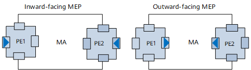
Inward-facing MEP: sends packets to other interfaces on the same device.
Outward-facing MEP: sends packets out of the interface on which the MEP is configured.
Maintenance Association Intermediate Point
MIPs are located on a link between two MEPs within an MD, facilitating management. More MIPs result in easier network management and control. Carriers set up more MIPs for important services than for common services.
MIP creation modes
MIPs can be automatically generated based on rules or manually created on interfaces. Table 1 describes MIP creation modes.
Creation Mode |
Description |
|---|---|
Manual configuration |
Only IEEE Std 802.1ag-2007 supports manual MIP configuration. The MIP level must be set. Manually configured MIPs are preferable to automatically generated MIPs. Although configuring MIPs manually is easy, managing many manually configured MIPs is difficult and errors may occur. |
Automatic creation |
A device automatically generates MIPs based on configured creation rules. Configuring creation rules is complex, but properly configured rules ensure correct MIP settings. The following part describes automatic MIB creation principles. |
Automatic MIP creation principles
A device automatically generates MIPs based on creation rules, which are configurable. Creation rules are classified as explicit, default, or none rules, as listed in Table 2.
Version |
Manually Configured MIPs Exist on an Interface |
Creation Rule |
MEPs Are Configured for Low-Level MDs |
MIPs Are Created |
|---|---|---|---|---|
IEEE Std 802.1ag-2007 |
Yes |
- | - | No |
No |
Default |
No |
Yes |
|
Explicit |
Yes |
Yes |
||
None |
- | - |

Identify a service instance associated with the MD.
Query all interfaces in the service instance and check whether MEPs are configured on these interfaces.
Query levels of all MEPs and locate the MEP with the highest level.
MIPs are separately calculated in each service instance such as a VLAN. In a single service instance, MAs in MDs with different levels have the same VLAN ID but different levels.
Each MD on a single interface has a specific level and is associated with multiple creation rules. The creation rule with the highest priority applies. An explicit rule has a higher priority than a default rule, and a default rule takes precedence over a none rule.
The level of a MIP must be higher than any MEP on the same interface.
An explicit rule applies to an interface only when MEPs are configured on the interface.
A single MIP can be generated on a single interface. If multiple rules for generating MIPs with different levels can be used, a MIP with the lowest level is generated.
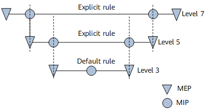
MIP creation rules help detect and locate faults by level.
For example, CCMs are sent to detect a fault in a level 7 MD on the network shown in Figure 4. Loopback or linktrace is used to locate the fault in the link between MIPs that are in a level 5 MD. This process is repeated until the faulty link or device is located.
The following example illustrates how to create a MIP based on a default rule defined in IEEE Std 802.1ag-2007.
On the network shown in Figure 5, MD1 through MD5 are nested in MD7, and MD2 through MD5 are nested in MD1. MD7 has a higher level than MD1 through MD5, and MD1 has a higher level than MD2 through MD5. Multiple MEPs are configured on Device A in MD1, and the MEPs belong to MDs with different levels.
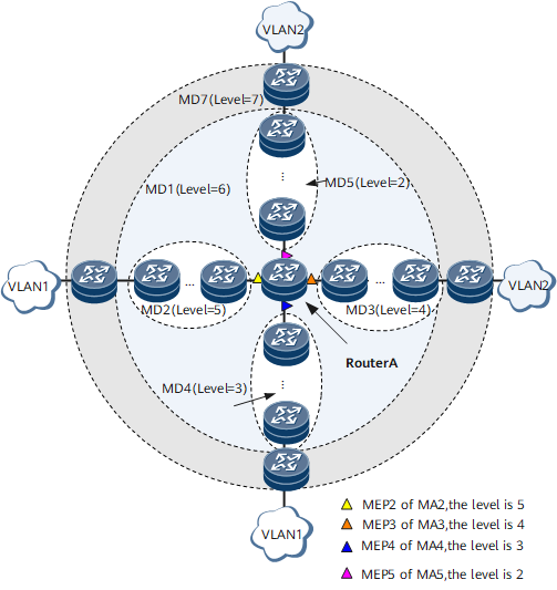
A default rule is configured on Device A to create a MIP in MD1. The procedure for creating the MIP is as follows:
Device A compares MEP levels and finds the MEP at level 5, the highest level. The MEP level is determined by the level of the MD to which the MEP belongs.
Device A selects the MD at level 6, which is higher than the MEP of level 5.
Device A generates a MIP at level 6.
If MDs at level 6 or higher do not exist, no MIP is generated.
If MIPs at level 1 already exist on Device A, MIPs at level 6 cannot be generated.
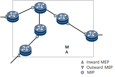
Hierarchical MP Maintenance
MEPs and MIPs are maintenance points (MPs). MPs are configured on interfaces and belong to specific MAs shown in Figure 6.
The scope of maintenance performed and the types of maintenance services depend on the need of the organizations that use carrier-class Ethernet services. These organizations include leased line users, service providers, and network carriers. Users purchase Ethernet services from service providers, and service providers use their networks or carrier networks to provide E2E Ethernet services. Carriers provide transport services.
Figure 7 shows locations of MEPs and MIPs and maintenance domains for users, service providers, and carriers.
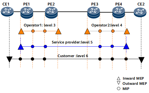
Operator 1, operator 2, the service provider, and the customer use MDs with levels 3, 4, 5, and 6, respectively. A higher MD level indicates a larger MD.
CFM Packet Format
CFM sends tagged protocol packets to detect link faults. Figure 8 shows the CFM packet format.
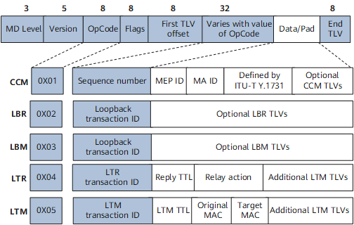
Table 3 describes the fields in a CFM packet.
Field |
Description |
|---|---|
MD Level |
Level of an MD. The value ranges from 0 to 7. A larger value indicates a higher level. |
Version |
Number of the CFM version. The current version is 0. |
OpCode |
Message code value, specifying a specific type of CFM packet. Table 4 describes the types of CFM packets. |
Varies with value of OpCode |
Variables of message codes. |
OpCode Value |
Packet Type |
Function |
|---|---|---|
0x01 |
Continuity check message (CCM) |
Used for monitoring E2E link connectivity. |
0x02 |
Loopback reply (LBR) message |
Reply to a Loopback message (LBM). LBRs are sent by local nodes enabled with loopback. |
0x03 |
Loopback message (LBM) |
Sent by an interface that initiates loopback detection. |
0x04 |
Linktrace reply (LTR) message |
Reply to a Linktrace message (LTM). LTRs are sent by local nodes enabled with linktrace. |
0x05 |
Linktrace message (LTM) |
Sent by an interface to initiate a linktrace test. |