CEs Connecting to the MPLS VPN over GRE Tunnels
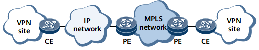
To connect a CE to an MPLS VPN, you must use a physical link to directly connect the CE to a PE on the MPLS backbone network. Specifically, the CE and PE must be on the same network. In this networking, you must associate the VPN with the physical interface connecting the PE to the CE.
As shown in Figure 1, not all CEs and PEs can be directly connected over physical links in actual networking. For example, for multiple organizations that connect to the Internet or IP backbone network, their CEs and PEs are geographically dispersed and cannot directly access the PEs on the MPLS backbone network. These organizations cannot directly access the sites inside the MPLS VPN through the Internet or IP backbone network.
To connect a CE to the MPLS VPN and ensure data transmission security, use the public network or a private network to connect the CE to a PE on the MPLS backbone network and establish a GRE tunnel between the CE and PE. The GRE tunnel can be regarded as a physical interface. You can associate the VPN with the interface on the PE.
When a GRE tunnel is used to access an MPLS VPN, GRE can be implemented in the following modes:
GRE of the private network: The GRE tunnel is associated with a certain VPN instance; the source and destination addresses of the GRE tunnel belong to this VPN instance.
GRE across the public network: The GRE tunnel is associated with a certain VPN instance; the source and destination addresses of the GRE tunnel are public network addresses, which do not belong to this VPN instance.
GRE across the VPN: The GRE tunnel is associated with a certain VPN instance, such as VPN1; the source interface of the GRE tunnel is bound to another VPN instance, such as VPN2. The GRE tunnel passes through VPN2.
GRE of the Private Network
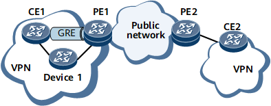
On the network shown in Figure 2, the source and destination addresses of the GRE tunnel belong to the private network. Establishing another tunnel to PE1 on the VPN is not cost-effective, and therefore you are advised to use Device 1 as a CE.
GRE Across the Public Network
In this networking, a CE and a PE must have interfaces that belong to the public network. The interfaces must use public network IP addresses. The CE must have routes to PEs in its public network routing table, and the PE must also have routes to CEs in its public network routing table.
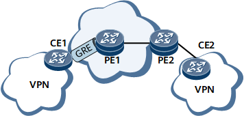
To transmit private network traffic from CEs to PEs over the tunnel, the outbound interface of the route to the remote site segment must be the GRE tunnel interface, and the next hop must be the IP address of the tunnel interface.
GRE Across the VPN
GRE across the VPN is different from GRE across the public network. In GRE across the VPN, CEs connect to PEs over a VPN such as VPN2 rather than the public network. Specifically, both the outbound interface of the private network traffic from CEs to PEs and the outbound interface of the private network traffic returned from PEs to CEs belong to VPN2.
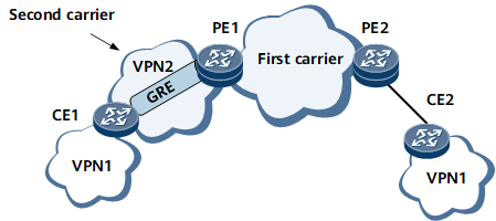
For example, in Figure 4, PE1 and PE2 are the edge devices of the first carrier on the MPLS backbone network. VPN2 is a VPN of the second carrier network. CE1 and CE2 are devices of customers.
To deploy a VPN based on the MPLS network in such a networking environment, such as VPN1, you can create a GRE tunnel across VPN2 between PE1 and CE1. CE1 and PE1 are then logically directly connected.