Proxy ARP
Principles
ARP is applicable only to devices on the same physical network. When a device on a physical network needs to send IP datagrams to another physical network, the gateway is used to query the routing table to implement communication between the two networks. However, routing table query consumes system resources and can affect other services. To resolve this problem, deploy proxy ARP on an intermediate device. Proxy ARP enables devices that reside on different physical network segments but on the same IP network to resolve IP addresses to MAC addresses. This feature helps reduce system resource consumption caused by routing table queries and improves the efficiency of system processing.
Implementation
Routed proxy ARP
A large company network is usually divided into multiple subnets to facilitate management. The routing information of a host in a subnet can be modified so that IP datagrams sent from this host to another subnet are first sent to the gateway and then to another subnet. However, this solution makes it hard to manage and maintain devices. If the gateways to which hosts are connected have different IP addresses, you can deploy routed proxy ARP on a gateway so that the gateway sends its own MAC address to a source host.
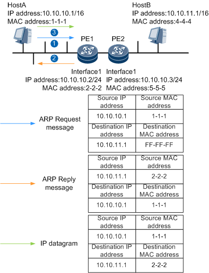
Figure 1 illustrates how routed proxy ARP is implemented between Host A and Host B.
- Host A sends an ARP request message for the MAC address of Host B.
- After the PE receives the ARP request message, the PE checks the destination IP address of the message and finds that it is not its own IP address and determines that the requested MAC address is not its MAC address. The PE then checks whether there are routes to Host B.
- If a route to Host B is available, the Interface1 checks whether routed proxy ARP is enabled.
- If routed proxy ARP is enabled on the PE, the PE sends the MAC address of its Interface 1 to Host A.
- If routed proxy ARP is not enabled on the PE, the PE discards the ARP request message sent by Host A.
- If no route to Host B is available, the PE discards the ARP request message sent by Host A.
- If a route to Host B is available, the Interface1 checks whether routed proxy ARP is enabled.
- After Host A learns the MAC address of the PE's Interface 1, Host A sends IP datagrams to the PE using this MAC address.
The PE receives the IP datagrams and forwards them to Host B:
Intra-VLAN proxy ARP
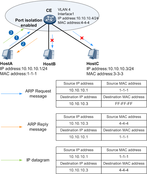
Figure 2 illustrates how intra-VLAN proxy ARP is implemented between Host A and Host C.

The type of interface1 could be VLANIF interface.
Host A, Host B, and Host C belong to the same VLAN, but Host A and Host C cannot communicate at Layer 2 because port isolation is enabled on the CE. To allow Host A and Host C to communicate, configure a interface1 on the CE and enable intra-VLAN proxy ARP.
- Host A sends an ARP request message for the MAC address of Host C.
- After the CE receives the ARP request message, the CE checks the destination IP address of the message and finds that it is not its own IP address and determines that the requested MAC address is not the MAC address of its Interface 1. The CE then searches its ARP table for the ARP entry indicating the mapping between the IP and MAC addresses of Host C.
- If the CE finds this ARP entry in its ARP table, the Interface1 checks whether intra-VLAN proxy ARP is enabled.
- If intra-VLAN proxy ARP is enabled on the CE, the CE sends the MAC address of its interface1 to Host A.
- If intra-VLAN proxy ARP is not enabled on the CE, the CE discards the ARP request message sent by Host A.
- If the CE does not find this ARP entry in its ARP table, the CE discards the ARP request message sent by Host A and checks whether intra-VLAN proxy ARP is enabled.
- If intra-VLAN proxy ARP is enabled on the CE, the CE broadcasts the ARP request message with the IP address of Host C as the destination IP address within VLAN 4. After the CE receives an ARP reply message from Host C, the CE generates an ARP entry indicating the mapping between the IP and MAC addresses of Host C.
- If intra-VLAN proxy ARP is not enabled on the CE, the CE does not perform any operations.
- If the CE finds this ARP entry in its ARP table, the Interface1 checks whether intra-VLAN proxy ARP is enabled.
- After Host A learns the MAC address of interface1, Host A sends IP datagrams to the CE using this MAC address.
The CE receives the IP datagrams and forwards them to Host C.
Inter-VLAN proxy ARP
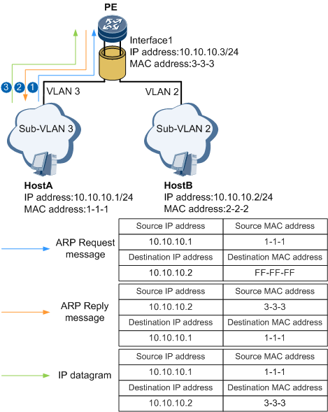
Figure 3 illustrates how inter-VLAN proxy ARP is implemented between Host A and Host B.
The type of interface1 could be VLANIF interface.
Host A belongs to VLAN 3, whereas Host B belongs to VLAN 2. Therefore, Host A cannot communicate with Host B. To allow Host A and Host B to communicate, configure interface1 on the PE and enable inter-VLAN proxy ARP.
- Host A sends an ARP request message for the MAC address of Host B.
- After the PE receives the ARP request message, the PE checks the destination IP address of the message and finds that it is not its own IP address and determines that the requested MAC address is not the MAC address of its interface1. The PE then searches its ARP table for the ARP entry indicating the mapping between the IP and MAC addresses of Host B.
- If the PE finds this ARP entry in its ARP table, the Interface1 checks whether inter-VLAN proxy ARP is enabled.
- If inter-VLAN proxy ARP is enabled on the PE, the PE sends the MAC address of its interface1 to Host A.
- If inter-VLAN proxy ARP is not enabled on the PE, the PE discards the ARP request message sent by Host A.
- If the PE does not find this ARP entry in its ARP table, the PE discards the ARP request message sent by Host A and checks whether inter-VLAN proxy ARP is enabled.
- If inter-VLAN proxy ARP is enabled on the PE, the PE broadcasts the ARP request message with the IP address of Host B as the destination IP address within VLAN 2. After the PE receives an ARP reply message from Host B, the PE generates an ARP entry indicating the mapping between the IP and MAC addresses of Host B.
- If inter-VLAN proxy ARP is not enabled on the PE, the PE does not perform any operations.
- If the PE finds this ARP entry in its ARP table, the Interface1 checks whether inter-VLAN proxy ARP is enabled.
- After Host A learns the MAC address of interface1, Host A sends IP datagrams to the PE using this MAC address.
The PE receives the IP datagrams and forwards them to Host B:
Local proxy ARP
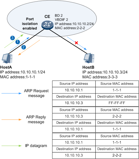
Figure 4 illustrates how local proxy ARP is implemented between Host A and Host B.
Host A and Host B belong to the same bride domain (BD) but cannot communicate at Layer 2 because port isolation is enabled on the CE. To enable Host A and Host B to communicate, a VBDIF interface (VBDIF 2) is configured on the CE to implement local proxy ARP.
Host A sends an ARP request message for the MAC address of Host B.
- After the CE receives the ARP request message, the CE checks the destination IP address of the message and finds that it is not its own IP address and determines that the requested MAC address is not the MAC address of VBDIF 2. The CE then searches its ARP table for the ARP entry indicating the mapping between the IP and MAC addresses of Host B.
- If the CE finds this ARP entry in its ARP table, the Interface1 checks whether local proxy ARP is enabled.
- If local proxy ARP is enabled on the CE, the CE sends the MAC address of VBDIF 2 to Host A.
- If local proxy ARP is not enabled on the CE, the CE discards the ARP request message.
- If the CE does not find this ARP entry in its ARP table, the CE discards the ARP request message and checks whether local proxy ARP is enabled.
- If local proxy ARP is enabled on the CE, the CE broadcasts an ARP request message to request Host B's MAC address. After receiving an ARP reply message from Host B, the CE generates an ARP entry for Host B.
- If local proxy ARP is not enabled on the CE, the CE does not perform any operations.
- If the CE finds this ARP entry in its ARP table, the Interface1 checks whether local proxy ARP is enabled.
- After Host A learns the MAC address of VBDIF 2, Host A sends IP datagrams to the CE using this MAC address.
The CE receives the IP datagrams and forwards them to Host B.
Usage Scenario
Table 1 describes the usage scenarios for proxy ARP.
Proxy ARP Type |
Usage Scenario |
|---|---|
Routed proxy ARP |
Two hosts that need to communicate belong to the same network segment but different physical networks. The gateways to which hosts are connected have different IP addresses. |
Intra-VLAN proxy ARP |
Two hosts that need to communicate belong to the same network segment and the same VLAN in which user isolation is configured. |
Inter-VLAN proxy ARP |
Two hosts that need to communicate belong to the same network segment but different VLANs. NOTE:
In VLAN aggregation scenarios, inter-VLAN proxy ARP can be enabled on the VLANIF interface corresponding to the super-VLAN to implement communication between sub-VLANs. |
Local proxy ARP |
In an EVC model, two hosts that need to communicate belong to the same network segment and the same BD in which user isolation is configured. |
Benefits
Proxy ARP offers the following benefits:
Proxy ARP enables a host on a network to consider that the destination host is on the same network segment. Therefore, the hosts do not need to know the physical network details but can be aware of the network subnets.
All processing related to proxy ARP is performed on a gateway, with no configuration needed on the hosts connecting to it. In addition, proxy ARP affects only the ARP tables on hosts and does not affect the ARP table and routing table on a gateway.
Proxy ARP can be used when no default gateway is configured for a host or a host cannot route messages.