Understanding E-STP
Enhanced STP (E-STP) considers a pseudo wire (PW) an abstract interface and allows it to participate in MSTP calculation to eliminate loops. E-STP prevents loops and duplicate traffic on inter-AS VPLS networks or CE dual-homing scenarios. The following section describes how to implement E-STP by deploying STP on the AC side or PW side.

Unless otherwise specified, STP in this document includes STP defined in IEEE 802.1D, RSTP defined in IEEE 802.1W, and MSTP defined in IEEE 802.1S.
STP Deployment on the AC Side
STP can be deployed on the AC side to resolve duplicate traffic reception problems on remote PEs and upstream traffic load balancing problems on CEs.
Background
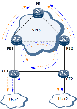
On the network shown in Figure 1, users access the VPLS network through a ring network that is comprised of CE1, CE2, PE1, and PE2. The PEs are fully connected on the VPLS network. The packet forwarding process is as follows (using the forwarding of broadcast or unknown unicast packets from CE1 as an example):
After CE1 receives a broadcast or unknown unicast packet, it forwards the packet to both PE1 and CE2.
After PE1 (CE2) receives the packet, it cannot find the outbound interface based on the destination MAC address of the packet, and therefore broadcasts the packet.
After PE2 receives the packet, it also broadcasts the packet. Because PEs do not forward data received from a PW back to the PW, PE2 (PE1) sends the packet to a CE and the remote PE.
As a result, a loop occurs on the path CE1 -> CE2 -> PE2 -> PE1 -> CE1 or the path CE1 -> PE1 -> PE2 -> CE2 -> CE1. The CEs and PEs all receive duplicate traffic.
Solution
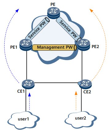
To address this problem, enable STP on CE1, CE2, PE1, and PE2; deploy an mPW between PE1 and PE2, deploy a service PW between PE1 and the PE and between PE2 and the PE, and associate service PWs with the mPW; enable MSTP for the mPW and AC interfaces so that the mPW can participate in STP calculation and block a CE interface to prevent duplicate traffic. In addition, configure PE1 and PE2 as the root bridge and secondary root bridge so that the blocked port resides on the link between the CEs.
As shown in Figure 2, STP is enabled globally on PE1, PE2, CE1, and CE2; an mPW is deployed between PE1 and PE2; STP is enabled on GE 1/0/1 on PE1 and PE2 and on GE 1/0/1 and GE 1/0/2 on CE1 and CE2. PE2 is configured as the primary root bridge and PE1 is configured as the secondary root bridge (determined by the bridge priority) to block the port connecting CE2 to CE1. After STP calculation and association between the mPW and service PWs are implemented, remote devices no longer receive duplicate traffic.
Reliability
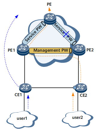
On the network shown in Figure 3 the mPW does not detect a fault on the link between the PE and PE2 because PE1 is reachable to the PE and a new service PW can be created. In addition, the STP topology remains unchanged, and therefore the blocked port is unchanged and STP recalculation is not required.
If the STP topology changes, each node sends a TCN BPDU to trigger the updating of local MAC address entries. In addition, the TCN BPDU triggers the PW to send MAC Withdraw packets to instruct the remote device to update the learned MAC address entries locally. In this manner, traffic is switched to an available link.
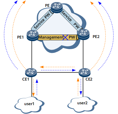
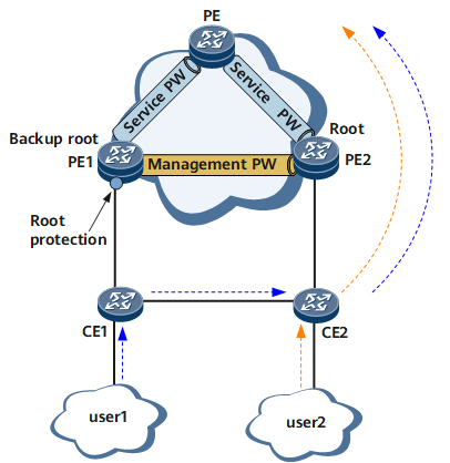
As shown in Figure 4, if the mPW between PE1 and PE2 fails, the ring network topology is recalculated, and the blocked port on CE2 is unblocked and enters the Forwarding state. In this situation, the remote PE receives permanent duplicate packets.
To resolve this problem, configure root protection on the secondary root bridge PE1's GE 1/0/1 connecting to CE1. As shown in Figure 5, if the mPW between PE1 and PE2 fails, PE1's GE 1/0/1 is blocked because it receives BPDUs with higher priorities. As the link along the path PE1 -> CE1 -> CE2 -> PE2 is working properly, PE1's blocked port keeps receiving BPDUs with higher priorities, and therefore this port remains in the blocked state. This prevents the remote PE from receiving duplicate traffic.
Load balancing
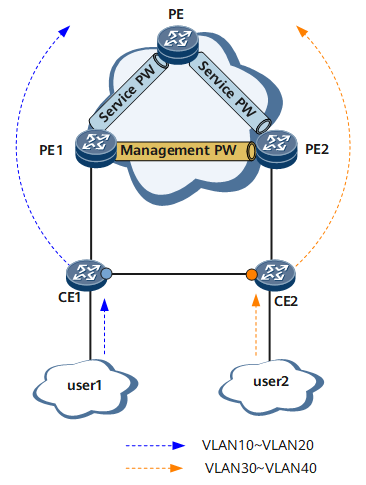
As shown in Figure 6, MSTP is enabled for ports connecting PEs and CEs, for the mPW between PE1 and PE2, and for ports connecting CE1 and CE2. MSTP is globally enabled on PE1, PE2, CE1, and CE2. After PE1 is configured as the primary root bridge and PE2 is configured as the backup root bridge (determined by bridge priority), MSTP calculation is performed to block the port connecting CE1 and CE2. A mapping is configured between VLANs and MSTIs to implement load balancing.
STP Deployment on the PW Side
STP can be deployed on the PW side to eliminate loops on inter-AS VPLS networks and resolve duplicate traffic reception problems on the remote PE and upstream traffic load balancing problems on CEs. Currently, E-STP applies only to inter-AS VPLS Option A.
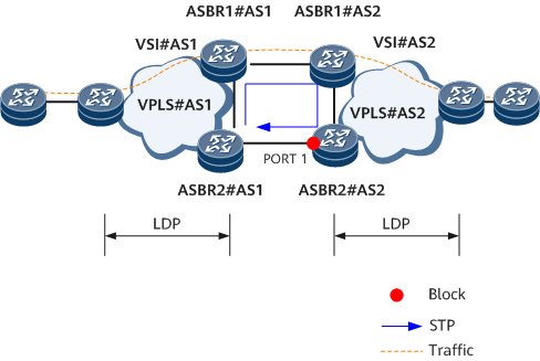
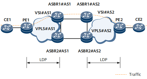
Figure 7 shows an inter-AS VPLS Option A network.
ASBRs in different VPLS ASs (Metro-E areas) are connected back to back. ASBR1#AS1, which functions as the CPE of ASBR1#AS2, accesses VSI#AS2; ASBR1#AS2, which functions as the CPE of ASBR1#AS1, accesses VSI#AS1. A VPLS or HVPLS network is set up in VPLS#AS1 and VPLS#AS2 (Metro-E areas) by using LDP, and data is forwarded in the VSIs.
The local ASBR and the peer can be connected through PW interfaces, Layer 2 physical interfaces, and Layer 3 physical interfaces. The peer ASBR is connected to the local ASBR as a CE.
A ring network exists in between VPLS#AS1 and VPLS#AS2.
Option A problem
In inter-AS VPLS Option A mode, redundant connections are established between ASs, and broadcast and unknown unicast packets may be forwarded in a loop. As shown in Figure 7, VPLS#AS1 and VPLS#AS2 are connected by two links to improve reliability. After Option A is adopted, fully connected PWs between PEs and ASBRs in an AS are configured with split horizon to prevent loops, but broadcast and unknown unicast packets are looped between ASBRs. PEs receive duplicate packets even if ASBRs in a VPLS AS are not connected.
Dual protection of Option A
To resolve inter-AS loops, configure STP on ASBRs between ASs to break off the loops, as shown in Figure 8. STP is running on Layer 2 ports, so Layer 2 links are required. If Layer 2 links do not exist between ASBRs, PWs or Layer 3 ports must be added. STP blocks a link on the inter-AS ring network to prevent broadcast and unknown unicast packets from being forwarded in a loop and the remote PE from receiving duplicate traffic.
Application scenarios of Option A - loop breakoff and duplicate traffic
As shown in Figure 8, STP is enabled for inter-AS links, and ASBR1#AS1 is configured as the primary root bridge and ASBR2#AS1 is configured as the secondary root bridge (determined by bridge priority). All nodes exchange BPDUs with each other to calculate the roles of their ports. Port 1 of ASBR2#AS2 is blocked to break off the loop and prevent the remote devices on the VPLS network from receiving duplicate traffic.
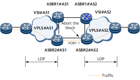
When a fault occurs on ASBR1#AS2, the topology changes, as shown in Figure 9. Each node recalculates the topology based on the received BPDUs and the blocked port 1 changes to the Forwarding state. As the network topology changes, each node sends a TCN BPDU to trigger the updating of local MAC address entries. In addition, the TCN BPDU triggers the PW to send MAC Withdraw packets to instruct the remote device to update the learned MAC address entries locally. In this manner, traffic is switched to an available link.
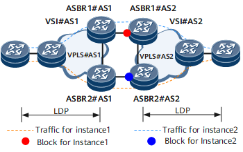
Application scenarios of Option A - load balancing
As shown in Figure 10, inter-AS ASBRs are connected through Layer 2 or Layer 3 interfaces. VLANs on an interface can be allocated to different instances by using the MSTP multi-instance feature. Then MSTP can block a port based on the instances. Each AS contains multiple MSTIs that are independent of each other. Therefore, load balancing can be implemented.
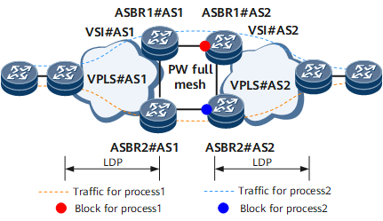
As shown in Figure 11, PWs between ASBRs are fully connected. By using the MSTP multi-process feature, E-STP associates mPWs with MSTP processes. Processes are independent of each other, and therefore the mPWs are independent of each other. Multiple service PWs are associated with an mPW. After the mPW is blocked, the associated service PWs are also blocked. This helps break off the loop between VPLS ASs and perform load balancing by blocking an interface as required.