Basic Concepts
Generalized Multiprotocol Label Switching (GMPLS) extends the traditional MPLS technology and applies to the transport layer. To seamlessly integrate the IP and transport layers, GMPLS extends MPLS labels and uses labels to identify Time Division Multiplexing (TDM) time divisions, wavelengths, and optical fibers, in addition to data packets. GMPLS adds labels to packets during IP data switching, TDM electrical circuit switching (primarily applying to Synchronous Digital Hierarchy [SDH]/Synchronous Optical Network [SONET]), and spatial switching. GMPLS separates control and data channels and uses the Link Management Protocol (LMP) to manage and maintain links. GMPLS supports multiple models for interconnecting the IP and transport networks, meeting requirements for IP and transport network convergence.
GMPLS Network Structure Models
GMPLS supports three models for connecting an IP network and a transport network: overlay model, peer model, and border peer model. The models are described as follows:
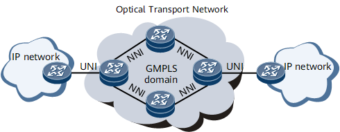
Overlay model: An IP network shown in Figure 1 functions as a client connected to a transport network and exchanges information only with directly connected optical transport devices. An IP network is unaware of path planning inside the transport network, and its network topology is independent of the transport network topology. GMPLS UNIs connect each IP network to the transport network. Users use specified UNIs on edge nodes of the IP networks to establish GMPLS tunnels across the transport network, but do not plan paths within the transport network on the edge nodes.
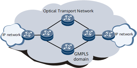
- Peer model: Figure 2 shows the peer model networking. IP devices and transport devices are operating in a single GMPLS domain. IP and transport network topologies are visible to each other. End-to-end (E2E) GMPLS tunnels can be established and they originate from an IP network, pass through a transport network, and are destined for another IP network.
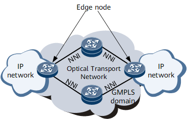
- Border peer model: Figure 3 shows the border peer model networking. A transport network and edge nodes that directly connect the IP networks to the transport network are in the same GMPLS domain. The transport network topology is invisible to non-edge nodes on the IP networks. A path for a GMPLS tunnel between the edge nodes across the transport network can be calculated.
Model |
Advantage |
Disadvantage |
|---|---|---|
Peer model |
Both IP address space and signaling protocols can be planned for transport devices and IP routers. The transport devices and IP routers can establish reliable connections. This model allows rapid service rollout and planning of E2E optimal paths. |
Using the peer model is difficult because the entire live network must be upgraded. Transport devices and IP routers need to use the same signaling protocols, increasing the possibility of security risks. |
Border peer model |
IP routers are isolated from transport devices, except for edge nodes. The transport network topology is visible to the boundary routers on the IP network. |
The edge nodes must have high performance. Security deteriorates in this model. This model does not support E2E optimal path planning. |
Overlay model |
Transport and IP network devices must have clearly defined UNI information. They do not need to learn about routing or topology information of each other or exchange information. The overlay model provides high security and has low upgrade requirements. |
Planning E2E optimal paths for GMPLS tunnels is difficult. UNI bandwidth usage is lower in this model than in the other two models. The overlay model requires UNI interface planning. |
The NetEngine 8000 F only supports the overlay model, in compliance with the GMPLS UNI model defined in relevant standards. The GMPLS UNI model is used in the following sections.
GMPLS UNI Model Structure and Concepts
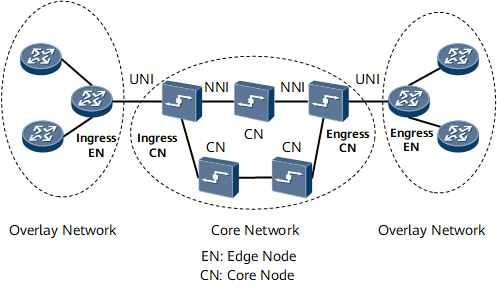
- Ingress EN: refers to an edge node that directly connects an IP network to a transport network. A GMPLS UNI tunnel originates from the ingress EN.
- Ingress CN: refers to an edge node that directly connects a transport network to the ingress EN.
- Egress EN: refers to an edge node that directly connects an IP network to a transport network. A GMPLS UNI tunnel is destined for the egress EN.
- Egress CN: refers to an edge node that directly connects a transport network to the egress EN.
- UNI: sends requests for bandwidth used for connections to the transport network.
- Network network interface (NNI): connects nodes within the transport network.
Separation Between the Control Channel and Data Channel
Traditional MPLS LSPs do not distinguish between the data channel and control channel. This means that both signaling and services travel through the same paths. GMPLS separates the data channel from the control channel. The control channel transmits control packets such as RSVP signaling packets and the data channel bears services. A fault in the control channel does not affect the data channel, ensuring uninterrupted service forwarding. The data and control channels are separated in either out-of-band or in-band mode. Out-of-band separation means that the data and control channels' physical links are separate. For example, the two channels use separate physical interfaces, time divisions, or wavelengths. In-band separation means that the data and control channels use the same physical links but different protocol overheads. For example, an Ethernet network uses OAM to carry control packets and an SDH network uses the dial control center (DCC) byte overheads to carry control packets. The NetEngine 8000 F only supports out-of-band Ethernet channels and in-band Ethernet OAM channels.
LMP
The Link Management Protocol (LMP) used in GMPLS manages links of the control and data channels. Relevant standards describe the major functions of LMP, including:
- Control channel management: Dynamic LMP automatically discovers neighbors and creates, maintains, and manages a control channel.
- Link attribute association: LMP bundles multiple data links between two directly connected nodes into a TE link, and synchronizes TE link attributes such as switching types and code types between the two directly connected nodes.
- Link connectivity verification: LMP verifies the connectivity of a data channel separated from a control channel. LMP can verify the connectivity of multiple data channels simultaneously.
- Fault management: LMP rapidly detects data link failures in unidirectional and bidirectional LSPs, locates and isolates faults, and triggers appropriate protection and recovery mechanisms. After a fault is removed, LMP sends a notification about link recovery. Fault management is performed on links only between adjacent nodes.
- Static LMP: LMP neighbors are manually configured and no LMP packet needs to be sent between them.
- Dynamic LMP: LMP neighbors, a control channel, a TE link, and data links are all automatically discovered, minimizing configurations and speeding up network construction.