UNI Tunnel Calculation Using Both IP and Optical PCE Servers
Background
IP service provision on E2E backbone networks faces the following
challenges:
- Optical and IP layers cannot share topology information. Therefore, path planning can only be manually performed at both the optical and IP layers. Optimizing path calculation and network resources is difficult.
- Inter-layer network deployment is performed by collaboration of IP and optical departments, which delays service rollout.
To face the preceding challenges, the NetEngine 8000 F uses both the IP Path Computation Element (PCE) and optical PCE functions to calculate paths for GMPLS UNI tunnels.
With this path calculation function, the IP and optical PCE servers automatically implement path planning, which reduces manual workload and speeds up service rollout.
Principles
An ingress EN on a GMPLS UNI functions as a PCE client and requests an IP PCE server to calculate paths. Upon receipt of the request, the IP PCE server works with an optical PCE server to calculate path and sends path information to the ingress EN. The ingress EN automatically establishes a GMPLS UNI tunnel over the calculated path.
In the following example, the IP and optical PCE servers
are used simultaneously to calculate a path for a GMPLS UNI tunnel
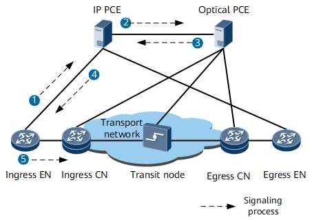
between the ingress EN and egress EN. The implementation is as follows:
- The ingress EN sends a delegate path request for a GMPLS UNI tunnel to an IP PCE server.
- Upon receipt of the request, the IP PCE server instructs the optical PCE server to calculate a path within an optical network.
- The optical PCE server sends path information to the IP PCE server.
- The IP PCE server sends all path information to the ingress EN.
- The ingress EN sends RSVP messages to the ingress CN and starts to establish a GMPLS UNI tunnel. The GMPLS UNI tunnel establishment process is similar to the common GMPLS UNI tunnel establishment process. The establishment procedure is not described.
Figure 1 Flowchart for using both the IP and optical PCE servers to
calculate paths
Benefits
Simultaneously using the IP and optical PCE servers to calculate
a path for a GMPLS UNI tunnel offers the following benefits:
- Automatically performs a great amount of site deployment planning, which reduces labor costs.
- Eliminates the collaboration between the IP and optical service departments, which speeds up site deployment.