Application Scenarios for L2TPv3
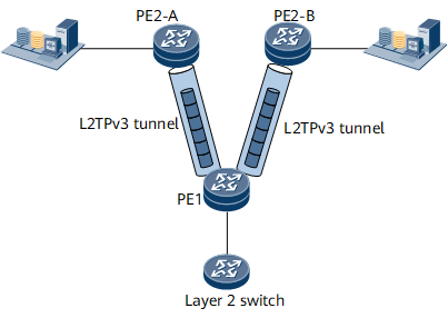
Figure 1 shows a scenario where Layer 2 Ethernet services are transmitted over L2TPv3 tunnels on a public IPv4/IPv6 network. To transmit Layer 2 Ethernet packets to the remote data center servers, an L2TPv3 tunnel is established between PE1 and PE2-A and between PE1 and PE2-B. Tags can be flexibly configured for user services accessing the L2TPv3 tunnels.
An Ethernet virtual connection (EVC) sub-interface on the downstream interface of PE1 serves as the L2TPv3 interface to provide access for users. This EVC sub-interface uses the default encapsulation type. The L2TPv3 tunnels support the following access modes:
- Whole-interface mode: The EVC sub-interface transparently transmits single-tagged, double-tagged, or untagged packets. In whole-interface access mode, the downstream interface is exclusively used by the EVC sub-interface.
- C-tag termination mode: The EVC sub-interface receives only user packets carrying C-tags and strips the C-tags of these packets before forwarding these packets to an L2TPv3 tunnel for transparent transmission.
- S-tag termination mode: The EVC sub-interface receives only user packets carrying S-tags and strips the S-tags of these packets before forwarding these packets to an L2TPv3 tunnel for transparent transmission.
- S-tag+C-tag termination mode: The EVC sub-interface receives only user packets carrying both C-tags and S-tags and strips the C-tags and S-tags of these packets before forwarding these packets to an L2TPv3 tunnel for transparent transmission.