Hard Pipe-based VPWS/VPLS
Principles
A logical hard pipe network can be defined if you specify hard-pipe attributes and reserve bandwidth resources on the network-side interfaces of PEs and the P. To provide users with IP hard-pipe leased line services, configure hard-pipe attributes for static PWs of a VPWS or VPLS.
To implement a P2P IP hard pipe, enable the IP hard pipe function for the static PW of a VPWS.
To implement an MP2MP IP hard pipe, enable the IP hard pipe function for static PWs of a VPLS.
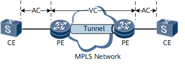
A hard pipe-based VPWS and a hard pipe-based VPLS use the same IP hard pipe scheduling model and tunnel type. After a carrier determines the PEs for user access on the NMS and plans a transmission path, a hard-pipe TE tunnel can be established between the PEs. The carrier can use the NMS to reserve a section of hard-pipe bandwidth for each node along the TE tunnel based on committed user access bandwidth and establish PWs to be bound to the TE tunnel.
A hard pipe-based VPWS and a hard pipe-based VPLS require different configurations of IP hard pipe bandwidth. For a hard pipe-based VPLS, establish PWs to connect different access sites on multiple PEs and restrict access bandwidth for the PWs. For a hard pipe-based VPWS, establish a PW to connect different access sites on two PEs and restrict access bandwidth for the PW. In this way, both a hard pipe-based VPWS and a hard pipe-based VPLS ensure sufficient bandwidth and low delay for leased line services.
DiffServ Model
IP hard pipe VPWS services use the pipe enhanced model. When hard pipe attributes are configured, VPWS services are switched to the pipe enhanced model. Therefore, you do not need to configure the DiffServ command separately. The commands for configuring hard pipe attributes and a DiffServ mode are mutually exclusive. Therefore, you cannot manually change the DiffServ mode for TE LSPs.
The uniform mode is configured on the PE's user-to-network inbound interface to identify user data, differentiating priorities and mapping VC label priorities. The pipe mode is used on the PE's network-to-user outbound interface to process user data, without changing the user packet priorities.
Bandwidth Expansion for Hard Pipe-based VPWS
In compliant with the VPWS/PWE3 service packet encapsulation standards, the outbound interface on the public network encapsulates a public network header to access user packets before sending them out. Therefore, the packet length is increased, and the access user bandwidth must be increased on the public network side.
The NMS must reserve bandwidth for the hard pipe on the public network side based on the expanded access user bandwidth.
In this example, the length of packets received on a PE from a CE is L1 (CRC length included). The length of the packets sent by the PE to the public network interface is L2. The public network interface is an Ethernet interface that sends double-tagged packets. The L2 is calculated as follows:
L2 = L1 + Public network header length (length of the destination MAC address, source MAC address, Eth_Type, outer VLAN tag, inner VLAN tag, TE label, and VC label)
L2 = L1 + 30
- User packet length
- Public network link type
The user data packet length varies. Even in the data flow from the same access user, packets are of varied lengths. Therefore, there is no fixed and accurate bandwidth expansion proportion on Ethernet links. However, the bandwidth expansion proportion can be calculated based on the average packet length.
The VPWS bandwidth expansion proportion parameters can be configured. The default value is calculated based on the average parameter values:
1. User packet length
The average packet length of 300 bytes is used as the default packet length.
2. Public network link type
The public network interface uses Ethernet encapsulation and sends packets carrying double VLAN tags.
The default bandwidth expansion proportion is: 30/300 = 10%