EVPN Fundamentals
Typical EVPN Networking
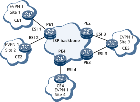
As shown in Figure 1, an EVPN has a similar network structure to a BGP/MPLS IP VPN. In EVPN networking, to implement interconnection between sites, PEs have an EVPN instance created on a carrier backbone network, connect to CEs at different sites, and establish EVPN BGP peer relationships and MPLS/SR tunnels with each other. Different from a BGP/MPLS IP VPN, an EVPN uses Layer 2 networks within sites. As such, a PE learns MAC addresses rather than IP routes from the CEs at a site, and then advertises these MAC addresses to the other sites within the same EVPN instance using EVPN-specific routes.
In EVPN networking, a CE can be single-homed to one PE or multi-homed to several PEs. As shown in Figure 1, CE1, CE2, and CE4 are single-homed to PE1, while CE3 is multi-homed to PE2 and PE3. Load balancing is supported in CE multi-homing networking.
EVPN technology defines a unique Ethernet Segment Identifier (ESI) on PEs to identify connections to the same CE. The PE interfaces must use the same ESI to connect to a CE and different ESIs to different CEs. During route advertisement between PEs, a PE can be aware of the other PEs connecting to the same CE after receiving routes that carry the same ESI.

A PE can use both IPv4 and IPv6 addresses to establish EVPN peer relationships with the other PEs. MPLS/VXLAN/SR tunnels can be deployed between IPv4 EVPN peers to carry services, and SRv6 tunnels need to be deployed between IPv6 EVPN peers to carry services. A PE sends the EVPN routes that carry SIDs only to IPv6 EVPN peers and the EVPN routes that do not carry SIDs only to IPv4 EVPN peers.
EVPN Routes
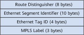
Ethernet auto-discovery route: also known as the Ethernet A-D route. PEs advertise Ethernet auto-discovery routes after establishing an EVPN BGP peer relationship. A local PE advertises such routes to other PEs to notify the reachability of MAC addresses of sites connected to the local PE. Ethernet A-D routes are classified into per-ES routes and per-EVI routes. Ethernet A-D per-ES routes are used for fast convergence, redundancy mode, and split horizon. Ethernet A-D per-EVI (EVPN Instance) routes are used for aliasing. Figure 2 shows the NLRI of an Ethernet A-D route.
The description of each field is as follows:Route Distinguisher: In an Ethernet A-D per-ES route, this field contains the source IP address set on a PE, for example, X.X.X.X:0. In an Ethernet A-D per-EVI route, this field is the RD of an EVPN instance.
Ethernet Segment Identifier: uniquely identifies connections between PEs and a CE.
Ethernet Tag ID: The value of the field is all Fs in Ethernet A-D per-ES routes. In an Ethernet A-D per-EVI route, this field identifies a sub-broadcast domain in an ES. If this field is set to all 0s, the EVI contains only one broadcast domain. The value of this field is the same as the local service ID in an EVPN VPWS scenario.
MPLS Label: The value is all 0s for Ethernet A-D per-ES routes, in compliance with the standard. The value of this field for Ethernet A-D per-EVI routes is the MPLS label used to forward unicast traffic in load balancing mode.
Although the MPLS Label field of a per-ES route is all 0s according to the standard, by default, a device sets the MPLS Label field to an ESI label value. After the peer esad-route-compatible enable command is run on a device, the device advertises the Ethernet A-D per-ES routes with the MPLS Label field changed to all 0s.
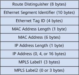
MAC/IP advertisement route: also known as the MAC/IP route. A MAC/IP advertisement route can carry the RD and ESI of an EVPN instance configured on the local PE and the VPN label assigned to the EVPN instance. Figure 3 shows the NLRI of a MAC/IP advertisement route. The MAC/IP advertisement route contains information, such as the RTs and next hop of the EVPN instance, in addition to the NLRI. This type of route can be used for the local PE to advertise unicast MAC/IP address reachability to the other PEs. For details, see Unicast MAC Address Transmission.
The description of each field is as follows:Route Distinguisher: RD of an EVPN instance.
Ethernet Segment Identifier: uniquely identifies connections between PEs and a CE.
Ethernet Tag ID: The value is all 0s in regular scenarios and the same as the BD tag value in VLAN-aware BD EVPN access scenarios.
MAC Address Length: length of a MAC address advertised in the route.
MAC Address: MAC address advertised in the route.
IP Address Length: mask length of a host IP address advertised in the route.
IP Address: host IP address advertised in the route.
MPLS Label1: label used for Layer 2 service traffic forwarding.
MPLS Label2: label used for Layer 3 service traffic forwarding.
The functions of MAC/IP advertisement routes on the control plane are as follows:Host MAC address advertisement
To implement Layer 2 service exchanges between hosts connected to two PEs, the two PEs need to learn host MAC addresses from each other. After a BGP EVPN peer relationship is established between the PEs, they exchange MAC/IP advertisement routes to advertise host IPv4 addresses to each other. The MAC Address Length and MAC Address fields identify a host MAC address.
Host ARP advertisement
A MAC/IP advertisement route carries both the MAC address and IP address of a host. Therefore, this route can be used to transmit host ARP entries between PEs. The MAC Address and MAC Address Length fields identify a host MAC address, and the IP Address and IP Address Length fields identify a host IP address. In this case, MAC/IP advertisement routes are also called ARP routes.
Host IP route advertisement
To implement Layer 3 service exchanges between IPv4 hosts connected to two PEs, the two PEs need to learn host IPv4 routes from each other. After a BGP EVPN peer relationship is established between the PEs, they exchange MAC/IP advertisement routes to advertise host IPv4 addresses to each other. The IP Address Length and IP Address fields carried in a MAC/IP advertisement route identify a host destination address, and the MPLS Label2 field must carry a label used for Layer 3 service forwarding. In such a scenario, MAC/IP advertisement routes are also called Integrate Routing and Bridge (IRB) routes.
An ARP route carries the following valid information: host MAC address, host IP address, and Layer 2 traffic forwarding label. IRB routes carry the following valid information: host MAC address, host IP address, Layer 2 traffic forwarding label, and Layer 3 traffic forwarding label. As a result, IRB routes include ARP routes and can be used to advertise both the host IP routes and host ARP entries.
Host ND information advertisement
A MAC/IP advertisement route can carry both a host MAC address and a host IPv6 address. Such routes can be used to transmit and advertise host ND entries between PEs. The MAC Address and MAC Address Length fields identify a host MAC address, and the IP Address and IP Address Length fields identify a host IPv6 address. In such a scenario, MAC/IP advertisement routes are also called ND routes.
Host IPv6 route advertisement
To implement Layer 3 service exchanges between IPv6 hosts connected to two PEs, the two PEs need to learn host IPv6 routes from each other. After a BGP EVPN peer relationship is established between the PEs, they exchange MAC/IP advertisement routes to advertise host IPv6 addresses to each other. The IP Address Length and IP Address fields carried in the MAC/IP advertisement route identify a host IPv6 destination address, and the MPLS Label2 field must carry a label used for Layer 3 service traffic forwarding. In such a scenario, MAC/IP advertisement routes are also called IRBv6 routes.
An ND route carries the following valid information: host MAC address, host IPv6 address, and Layer 2 traffic forwarding label. An IRBv6 route carries the following valid information: host MAC address, host IPv6 address, Layer 2 traffic forwarding label, and Layer 3 traffic forwarding label. As such, IRBv6 routes include ND routes and can be used to advertise both a host IPv6 route and ND entry.
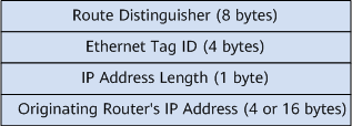
Inclusive multicast Ethernet tag route: also known as the IMET route. After a BGP peer relationship is established between PEs, the PEs exchange inclusive multicast routes. An inclusive multicast route carries the RD and route target (RT) of the EVPN instance on the local PE, source IP address (loopback address of the local PE) and provider multicast service interface (PMSI) information. The PMSI tunnel is used to carry the tunnel type (ingress replication or mLDP) and tunnel label used to transmit multicast packets. The PMSI and RT values are carried in routes as attributes, and the RD and source IP address are contained in NLRI information. Figure 4 shows the NLRI of an inclusive multicast route. BUM traffic includes broadcast, multicast, and unknown unicast traffic. Upon receipt of BUM traffic, a PE forwards it to the other PEs in P2MP mode. The PEs use the inclusive multicast routes to establish tunnels. For details, see BUM Packet Transmission.
The description of each field is as follows:Route Distinguisher: RD of an EVPN instance.
Ethernet Tag ID: The value is all 0s in regular scenarios and the same as the BD tag value in VLAN-aware BD EVPN access scenarios.
IP Address Length: length of a source IP address configured on the local PE.
Originating Router's IP Address: a field representing the source IP address configured on the local PE.
Currently, the EVPN source address on a PE can only be an IPv4 address. As such, this field is 4 bytes long.
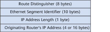
Ethernet segment route: carries the ESI, source IP address, and RD (source IP address:0) of the local PE. PEs connecting to the same CE use Ethernet segment routes to discover each other. This type of route is used in designated forwarder (DF) election. Figure 5 shows the NLRI of an Ethernet segment route.
The description of each field is as follows:Route Distinguisher: in the format of X.X.X.X:0. X.X.X.X indicates the EVPN source IP address configured on the local PE.
Ethernet Segment Identifier: uniquely identifies connections between PEs and a CE.
IP Address Length: length of a source IP address configured on the local PE.
Originating Router's IP Address: a field representing the source IP address configured on the local PE.
Currently, the EVPN source address on a PE can only be an IPv4 address. As such, this field is 4 bytes long.
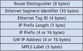
IP prefix route: used to advertise a host IP address received from an access network or the network segment where the host IP address resides. Figure 6 shows the NLRI of an IP prefix route.
The description of each field is as follows:Route Distinguisher: RD of an EVPN instance.
Ethernet Segment Identifier: uniquely identifies connections between PEs and a CE.
Ethernet Tag ID: Currently, this field can only be set to 0.
IP Prefix Length: mask length of an IP prefix carried in the route.
IP Prefix: IP prefix address.
GW IP Address: default gateway IP address.
MPLS Label: label used for Layer 3 service traffic forwarding.
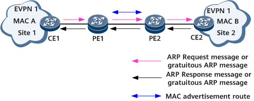
Unicast MAC Address Advertisement
Site 1 sends an ARP Request message or a gratuitous ARP message to advertise its MAC address (MAC A) and IP address to site 2. After the message arrives at PE1, PE1 generates a MAC/IP advertisement route for MAC A.Site
Site 2 responds to site 1 with an ARP Response message or a gratuitous ARP message carrying site 2's MAC address (MAC B) and IP address. After the message arrives at PE2, PE2 generates a MAC/IP advertisement route for MAC B.
PE1 and PE2 exchange MAC/IP advertisement routes that carry MAC addresses, next hops, and EVPN instance-based extended community attributes (such as RTs).
After PE1 and PE2 receive MAC/IP advertisement routes from each other, PE1 and PE2 find the corresponding EVPN instances based on the RT values carried in the routes. Then, PE1 and PE2 generate traffic forwarding entries in the EVPN instances based on the NLRIs carried in the routes for traffic transmission.
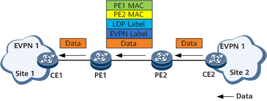
Unicast packet transmission
CE2 forwards unicast packets to PE2 at Layer 2.
Upon receipt of the unicast packets, PE2 encapsulates an EVPN label, a public-network LDP LSP label, PE2's MAC address, and PE1's MAC address in the order into the unicast packets. PE2 then forwards the encapsulated unicast packets to PE1.
After receiving the unicast packet after encapsulation, PE1 decapsulates the packet, locates the EVPN instance based on the EVPN label, searches the MAC table of the EVPN instance for an outbound interface mapped to the destination MAC address in the original packet, and forwards the unicast packet to the corresponding CE through the outbound interface.
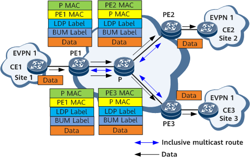
BUM Packet Transmission
CE1 sends BUM packets to PE1.
Upon receipt of the BUM packets, PE1 forwards them to PE2 and PE3 that belong to the same EVPN instance. Specifically, PE1 replicates each BUM packet and encapsulates an EVPN BUM label, public network tunnel label, PE1's MAC address, and P's MAC address into each packet, and sends the packets to the remote PE.
Upon receipt of the BUM packets, PE2 and PE3 decapsulate the BUM packets and send the BUM packets to the sites of the EVPN identified by the EVPN BUM label carried in the packets.
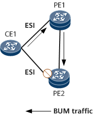
In the case where a CE is dual-homed to two PEs, based on the split horizon mechanism, an EVPN ESI label will be encapsulated into the BUM packets exchanged between the two PEs to prevent loops. As shown in Figure 10, CE1 is dual-homed to PE1 and PE2. After receiving a BUM packet from CE1, PE1 encapsulates the packet with an ESI and forwards the packet to PE2. When PE2 receives the BUM packet and finds that the ESI carried in the BUM packet is the same as the local ESI, PE2 discards the BUM packet to prevent a loop.