EVPN VPWS Fundamentals
Introduction
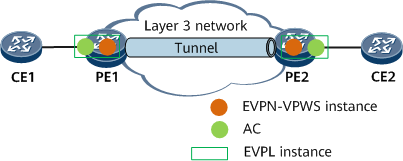
The EVPN virtual private wire service (VPWS) solution provides a P2P L2VPN service based on the EVPN service architecture. This solution reuses and simplifies the original EVPN technology, uses the MPLS tunnel technology to traverse the backbone network, and provides a Layer 2 packet forwarding mode for connections between access circuits (ACs) without searching for MAC forwarding entries.
- AC: an independent link or circuit that connects a CE to a PE. An AC interface can be a physical or virtual interface. The AC attributes include the encapsulation type, maximum transmission unit (MTU), and interface parameters of the specified link type.
- EVPL instance: An EVPL instance corresponds to an AC. Each EVPL instance has a service ID. An EVPL instance on the local PE corresponds to an EVPL instance on the remote PE. PEs exchange EVPN routes carrying a service ID to construct forwarding entries that are used to forward or receive service traffic from different ESs, achieving P2P interworking.
- EVPN VPWS instance: An EVPN VPWS instance is deployed on an edge PE and contains services that have the same access-side or network-side attributes. Routes are transmitted based on the RD and RT configured in each EVPN VPWS instance in a BGP EVPN address family.
- Tunnel: network-side MPLS tunnel or SR tunnel.
Compared with the conventional L2VPN VPWS solution, the EVPN VPWS solution simplifies the control and data models and uses BGP as the control plane where BGP route selection and the BGP next hop recursion are used to select traffic paths over backbone networks. This eliminates the need of specifying PWs.
Routes Used in EVPN VPWS
- Ethernet auto-discovery route: also known as the Ethernet A-D route. Ethernet A-D routes are classified into per-ES routes and per-EVI routes.
Ethernet auto-discovery per-ES routes: are sent by PEs on an EVPN VPWS network to notify the peer device of whether the local redundancy mode is single-active or all-active.
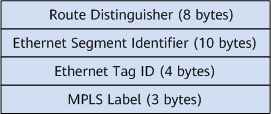
Ethernet auto-discovery per-EVI routes: are exchanged between PEs on an EVPN VPWS network to guide through Layer 2 traffic forwarding. Figure 2 shows the NLRI format of Ethernet A-D per-EVI routes.
The description of each field is as follows:Route Distinguisher: can be either the RD value of an EVPN instance or a combination of the source IP address configured on a PE and :0, such as X.X.X.X:0.
Ethernet Segment Identifier: uniquely identifies connections between PEs and a CE.
Ethernet Tag ID: local service ID of the EVPL instance on the local PE.
MPLS Label: For a non-SRv6 tunnel, this field is the EVPL label assigned based on each Ethernet A-D per-EVI route. For an SRv6 tunnel, this field is the SRv6 SID of this tunnel.
In addition to the NLRI, Ethernet A-D per-EVI routes also carry carries the Layer 2 extended community attribute that includes the following control fields:C: a control word identifier. If this field is set to 1, packets sent by the local PE must carry control information.
P: indicates whether the local PE is the master PE. In all-active scenarios, this control field must be set to 1.
B: indicates whether a PE is a backup PE in dual-homing single-active scenarios.
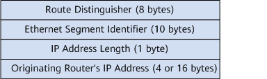
Ethernet Segment (ES) route: carries the RD, ESI, and source IP address of the local PE to implement automatic discovery and DF election between PEs connecting to the same CE. Figure 3 shows the NLRI of an Ethernet segment route.
The description of each field is as follows:Route Distinguisher: in the format of X.X.X.X:0. X.X.X.X indicates the EVPN source IP address configured on the local PE.
Ethernet Segment Identifier: uniquely identifies connections between PEs and a CE.
IP Address Length: length of a source IP address configured on the local PE.
Originating Router's IP Address: source IP address configured on the local PE.

Currently, the EVPN source address on the PE supports only IPv4. Therefore, the field contains only 4 bytes.
Protocol Packet Exchange Process in the Single-Homing Scenario
PE1 and PE2 are each configured with an EVPL instance and an EVPN VPWS instance. The EVPL instance must be bound to an AC interface and an EVPN VPWS instance, and each EVPL instance must be assigned a local service ID and a remote service ID. After the configuration, the local PE generates a forwarding entry indicating the association between the AC interface and EVPL instance.
PE1 and PE2 each send Ethernet A-D per-EVI routes to each other. An Ethernet A-D per-EVI route carries the RD, RTs, next-hop information, local service ID, and EVPL label or SRv6 SID.
PE1 and PE2 receive the Ethernet A-D per-EVI routes from each other, match the RTs of the routes, and import the routes to the corresponding EVPN VPWS instances. The routes then recure to an MPLS or SRv4 tunnel based on next hop information or to SRv6 tunnels based on SRv6 SIDs. If the service ID in the received routes is the same as the remote service ID configured for the local EVPL instance, a forwarding entry indicating the association between the MPLS or SRv4/v6 tunnel and local EVPL instance is generated.
Packet Exchange Process in Dual-Homing Single-Active Scenarios (with an E-Trunk Deployed)
Each PE is configured with an EVPL instance and an EVPN VPWS instance. The EVPL instance must be bound to an AC interface and an EVPN VPWS instance, and each EVPL instance must be assigned a local service ID and a remote service ID. After the configuration, the local PE generates a forwarding entry indicating the association between the AC interface and EVPL instance. The access-side interfaces on PE1 and PE2 must be configured with the same ESI.
PE1 and PE2 exchange ES routes that carry RDs, RTs, ESIs, and source IP addresses. After receiving the ES routes, PE1 and PE2 trigger DF election. The active/standby status of PE1 and PE2 is determined by the E-Trunk configured between PE1 and PE2. In this example, PE1 is the active device, and PE2 is the standby device.
PE1 and PE2 send PE3 the Ethernet A-D per-ES routes that carry the RD, RTs, next-hop information, and single-active mode information.
The PEs send each other the Ethernet A-D per-EVI routes that carry the RD, RTs, next-hop information, local service ID, EVPL label or SRv6 SID, and active/standby role.
Upon receipt of Ethernet A-D per-EVI routes from PE3, PE1 and PE2 match RTs of the corresponding EVPN VPWS instance and select an MPLS or SRv4 tunnel to perform traffic recursion based on the next-hop information or select an SRv6 tunnel to perform traffic recursion based on SRv6 SIDs. If the service ID in the received routes is the same as the remote service ID configured for the local EVPL instance, a forwarding entry indicating the association between the MPLS or SRv4/v6 tunnel and local EVPL instance is generated.
Upon receipt of EVI Ethernet AD routes from PE1 and PE2, PE3 matches RTs of the corresponding EVPN VPWS instance and select an MPLS or SRv4 tunnel to perform traffic recursion based on the next-hop information or select an SRv6 tunnel to perform traffic recursion based on SRv6 SIDs. If the service ID in the received routes is the same as the remote service ID configured for the local EVPL instance, an FRR entry indicating the association between the MPLS or SRv4/v6 tunnel and local EVPL instance is generated. The entry pointing to PE1 is the master entry, and the entry pointing to PE2 is the backup entry.
PE1 and PE2 each receive EVI Ethernet AD routes from each other and match the RTs of the corresponding EVPN VPWS instance. PE1 and PE1 then select an MPLS or SRv4 tunnel to perform traffic recursion based on the next-hop information or select an SRv6 tunnel to perform traffic recursion based on SRv6 SIDs. If the service ID in the received routes is the same as the remote service ID configured for the local EVPL instance, a bypass entry indicating the association between the MPLS or SRv4/v6 tunnel and local EVPL instance is generated.
Packet Exchange Process in Dual-Homing Single-Active Scenarios (with No E-Trunk Deployed)
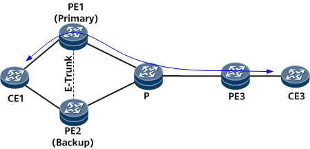
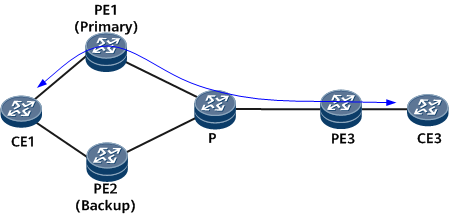
On the CE dual-homing network shown in Figure 5, PE1 and PE2 work in single-active mode and an E-Trunk is not deployed between them. The packet exchange process in this scenario is similar to that in the scenario with an E-Trunk deployed. The only difference is that the master/backup relationship between PE1 and PE2 in this scenario is determined by the DF election mechanism of EVPN VPWS.
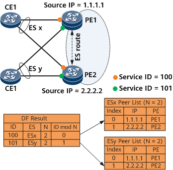
By default, the PE with a smaller source IP address is elected as the master DF. This, however, causes all service traffic to travel through the same PE, which may lead to unbalanced network load. To address this problem, enable service ID-based DF election. Using Figure 6 as an example, the service ID-based DF election process is as follows:
PE1 and PE2 send each other the ES routes that carry the RD, RT, ESI, and source IP address.
Upon receipt of ES routes, PE1 and PE2 construct PE lists based on different ESIs. The PEs in a PE list are ordered by the source IP address in ascending order, and the system assigns an index starting at 0 to each PE in ascending order.
Each ES corresponds to a local service ID. The system calculates the DF election result of each ES based on the formula (service ID mod N), where N indicates the number of PEs. As shown in Figure 6, the service ID corresponding to ESx is 100, the number of PEs (N) is 2, and the ESx is calculated out to be 0. The system searches the PE list of ESx for the index and finds that the DF election result of ESx is PE1. Similarly, the DF election result of ESy is PE2. This allows traffic from different Es to be transmitted over different PEs.
The DF election result determines the value of the P field in the A-D per-EVI routes sent by PE1 and PE2 to PE3. In this manner, PE3 is notified of the master/backup status of PE1 and PE2. Devices forward EVPN VPWS services, without distinguishing unicast traffic and BUM traffic. On the network shown in Figure 5, PE1 forwards upstream traffic from CE1, and PE2 blocks the traffic. PE1 forwards the downstream traffic of PE3, and PE2 blocks such traffic. If FRR is deployed for MAC routes between PE3 and each of PE1 and PE2, the downstream traffic sent to PE2 is forwarded to PE1 and then to CE1.
Protocol Packet Exchange Process in Dual-Homing Active-Active Scenarios
Each PE is configured with an EVPL instance and an EVPN VPWS instance. The EVPL instance must be bound to an AC interface and an EVPN VPWS instance, and each EVPL instance must be assigned a local service ID and a remote service ID. After the configuration, the local PE generates a forwarding entry indicating the association between the AC interface and EVPL instance. PE1 and PE2 are configured to work in all-active mode and the access-side interfaces of PE1 and PEs are assigned the same ESI.
PE1 and PE2 exchange ES routes that carry RDs, RTs, ESIs, and source IP addresses. PE1 and PE2 send ES routes that carry the RD, RT, ESI, and source IP address. Upon receipt of ES routes, PE1 and PE2 trigger DF election. The E-Trunk between PE1 and PE2 determines the master/backup relationship between PE1 and PE2. In an active-active scenario, the E-Trunk between PE1 and PE2 is in the master state.
PE1 and PE2 send PE3 the Ethernet A-D per-ES routes that carry the RD, RTs, next-hop information, and all-active mode information.
PEs send Ethernet A-D per-EVI routes to each other. An Ethernet A-D per-EVI route carries the RD, RTs, next hop, local service ID, EVPL label or SRv6 SID, and active/standby role.
Upon receipt of Ethernet A-D per-EVI routes from PE3, PE1 and PE2 match RTs of the corresponding EVPN VPWS instance and select an MPLS or SRv4 tunnel to perform traffic recursion based on the next-hop information or select an SRv6 tunnel to perform traffic recursion based on SRv6 SIDs. If the service ID in the received routes is the same as the remote service ID configured for the local EVPL instance, a forwarding entry indicating the association between the MPLS or SRv4/v6 tunnel and local EVPL instance is generated.
PE3 receives the Ethernet A-D per-EVI routes from PE1 and PE2, matches the RTs of the routes with the corresponding EVPN VPWS instances, and recurses the routes to MPLS or SRv4 tunnels based on next hop information or to SRv6 tunnels based on SRv6 SIDs. If the service ID of the received route is the same as the remote service ID configured for the local EVPL instance, load balancing entries are generated for the MPLS or SRv4/v6 tunnel and the local EVPL instance.
PE1 and PE2 receive Ethernet A-D per-EVI routes from each other, match the RTs of the routes, and import the routes to the corresponding EVPN VPWS instances. Then the routes recurse to MPLS or SRv4 tunnels based on next hop information or to SRv6 tunnels based on SRv6 SIDs. If the service ID of the received route is the same as the remote service ID and ESI configured for the local EVPL instance, a bypass entry is generated, indicating the association between the MPLS or SRv4/v6 tunnel and the local EVPL instance.
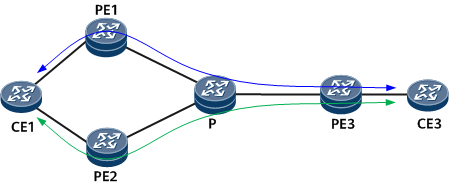
The data packets sent from AC-side interfaces are forwarded to the peer PE over the corresponding MPLS tunnel based on the forwarding entries indicating the association between tunnels and EVPL instances. Upon receipt of packets, the peer PE searches for the association entries based on the label encapsulated in the packets and the forwards the packets to the corresponding AC interface based on the association entries.